Karl Holtey – Blog Archive

February 20, 2012

Window to my Workshop 24

Filed under: No 982 Smoother plane,Window to my Workshop — Tags: , , , — admin @ 6:31 pm

No 982 smoothing plane in the making – 6

Picture shows bottom and sides ready for assembly. This is showing the blade kickers riveted in place, both handle risers already fixed and both bridges in place. Note that the blade kickers hold the blade central whilst lateral adjustment is being applied to the blade.

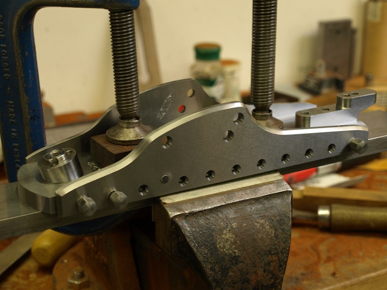
Sides now being fixed into place. Note the bottom is clamped to a bar during this process. This helps a lot in keeping things straight whilst the screws are given a final tightened up.

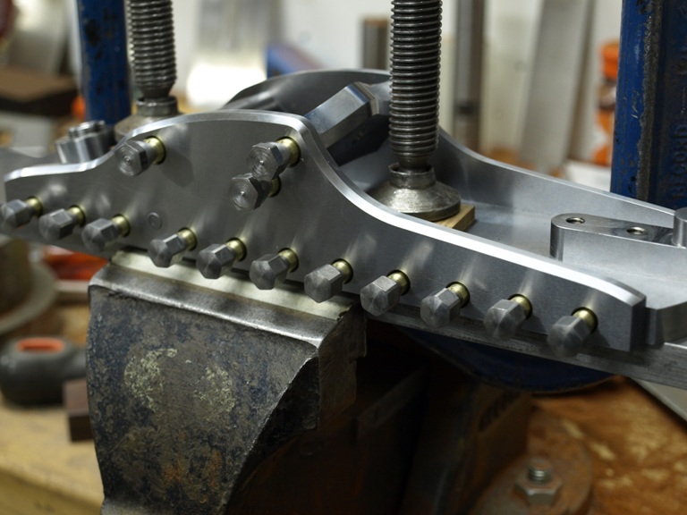
This picture shows the plane with the brass cones. The cones have not been tightened yet

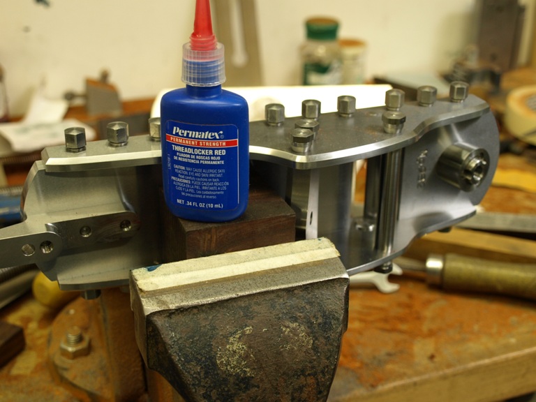
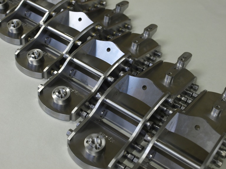
Showing the plane with all the screws tightened down. Now each screw is taken out one at a time, the locking compound applied and the screw retightened to its full torque.

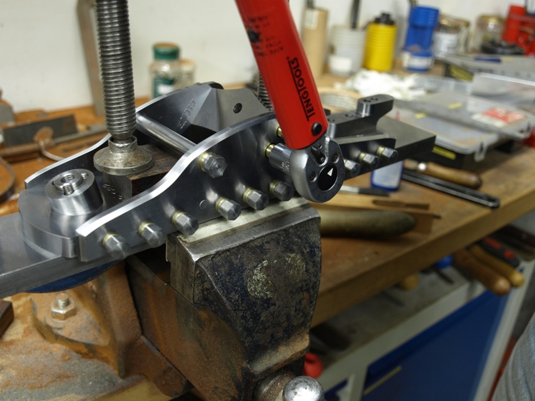
Torque wrench in use.

The planes starting to come together.

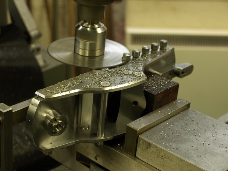
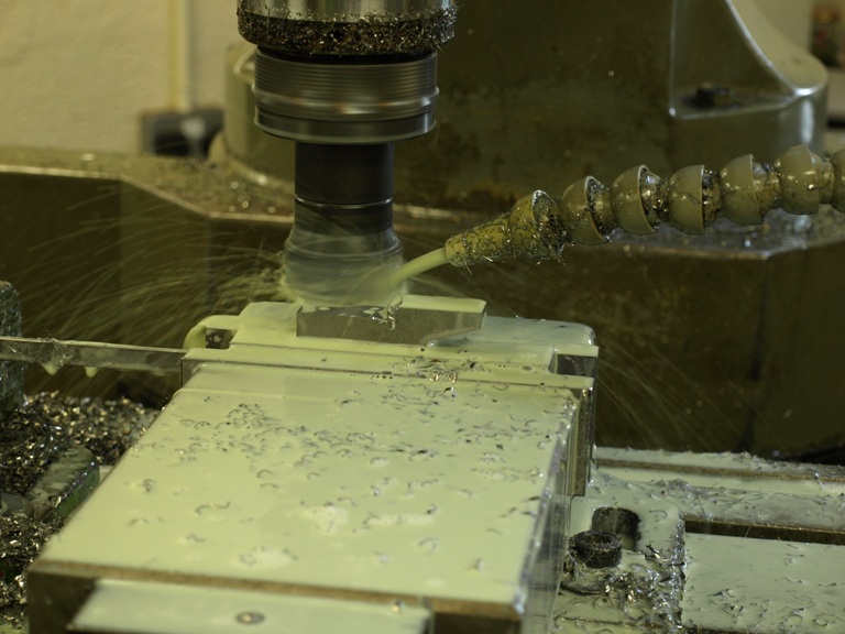
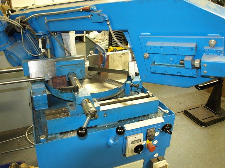
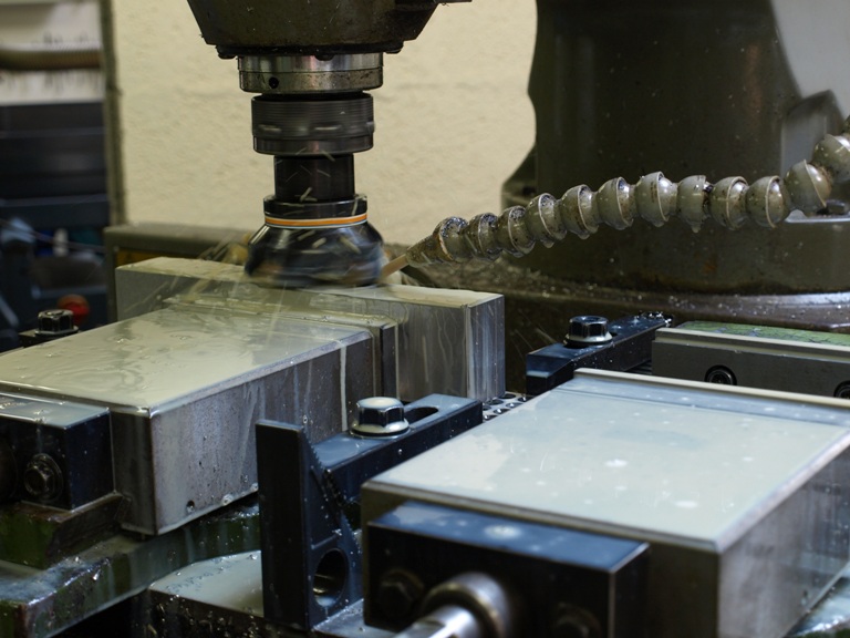
The bolts are now being chopped off with the slitting saw prior to milling and grinding

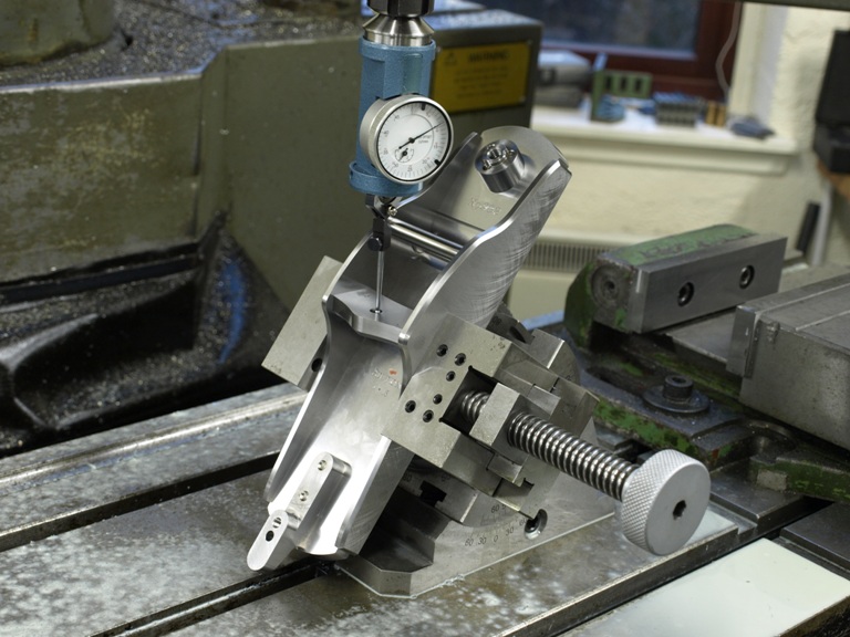
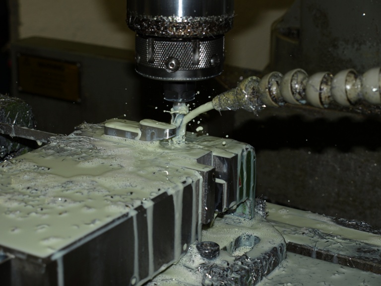
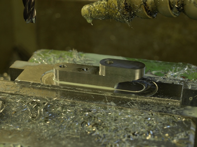
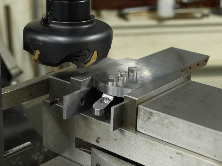
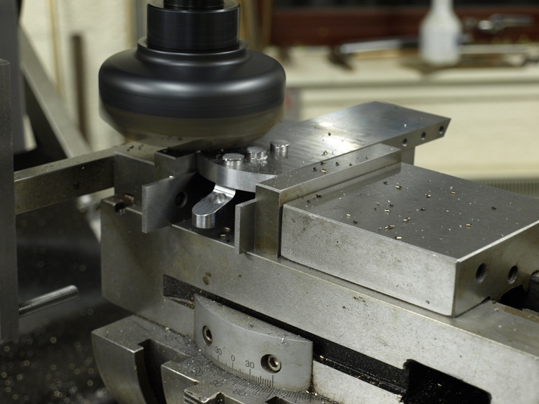
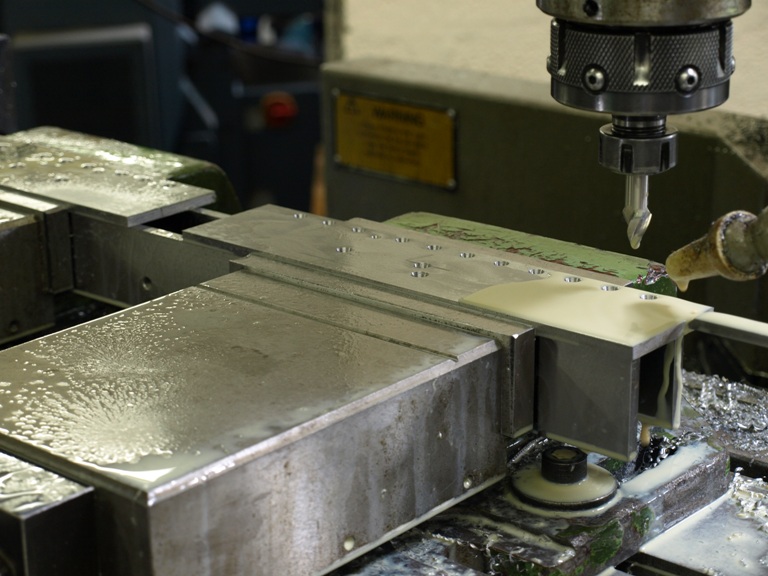
With the sides milled flush the adjuster bridge/bed can be reamed and then a shallow recess is milled in circular contour to make a bed for the adjuster. This is all done on exactly the same plane as the blade frog – as can be seen in the next picture.

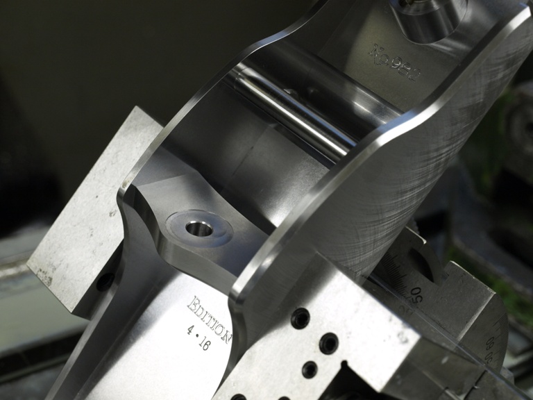
Showing the recess around the adjuster bore forming a true bed for the adjuster.

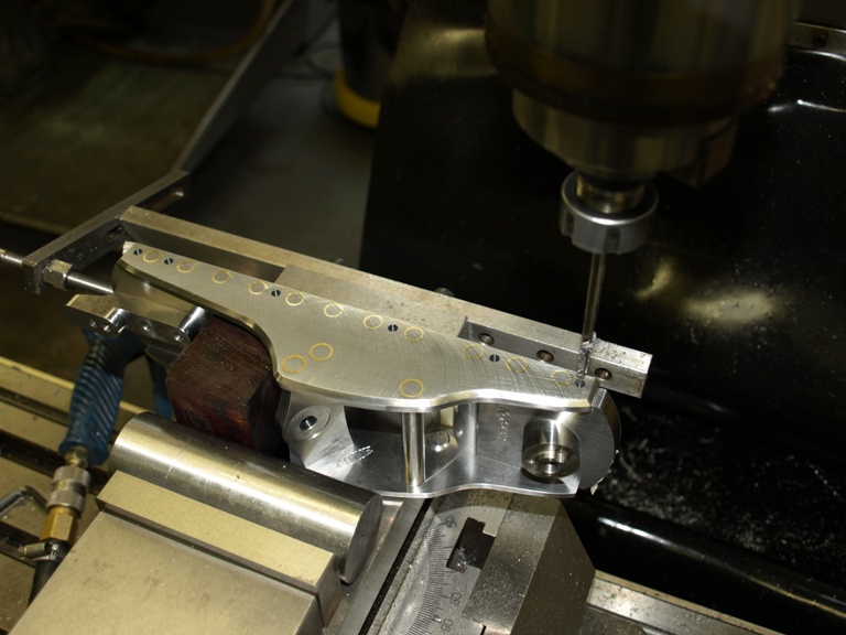
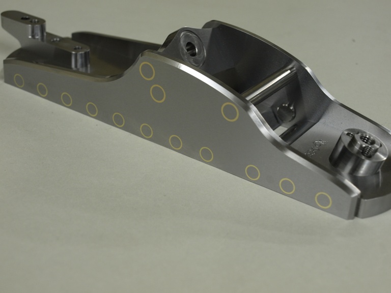
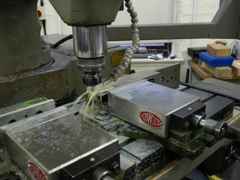
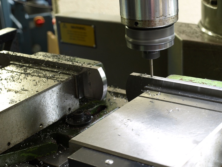
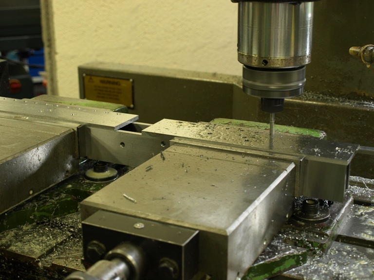
Though all the fixing appears to be complete there is still the drilling and reaming for the taper pins to go into their 6 positions. This maintains a positive lock between the bottom and the sides, as seen on the picture. The reason for this is just a bit of extra insurance against any movement caused by impact.

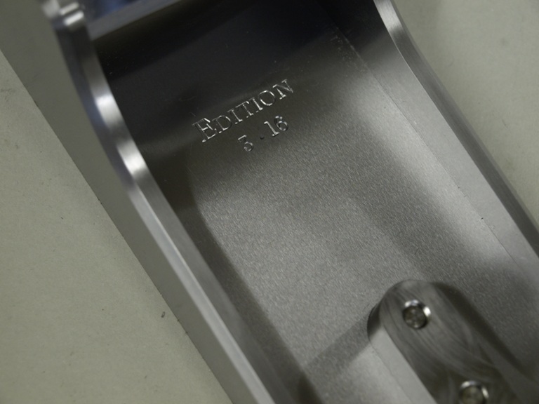
Picture showing the internal grinding texture which is a pleasant by-product of all the grinding and truing up at the beginning of the project.

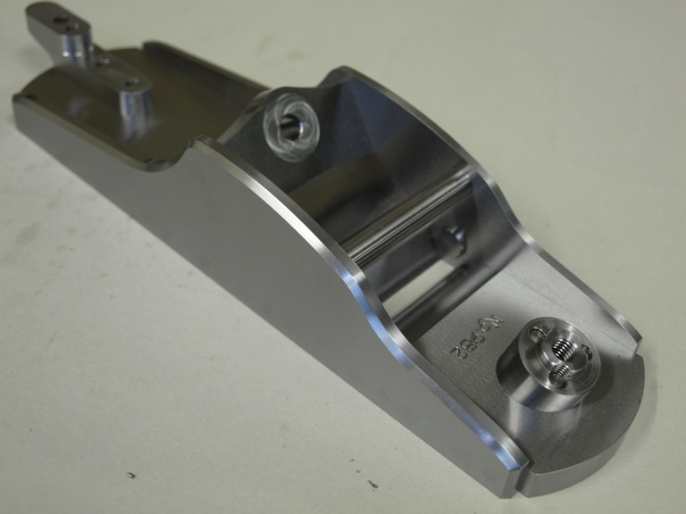
Body without the cones

Body with the cones.
Window to my Workshop 23

Filed under: No 982 Smoother plane,Window to my Workshop — Tags: , , , — admin @ 5:53 pm

No 982 smoothing plane in the making - 5

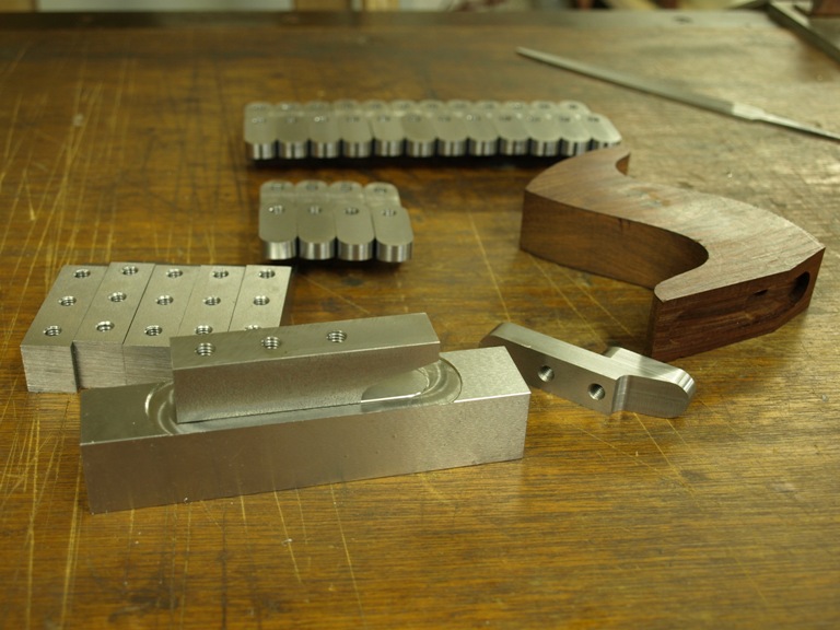
There are 24 handle risers being ground true. Made in pairs joined end to end for ease of working.

The handle riser having been parted from its partner is now having its step milled into it.

With the step now formed ready for the radiuses

The radiuses being rough cut

The radiuses now with the finishing cut (three radiuses in total).

Handle riser now complete.

Showing pre-worked handle risers with one on its machining carrier and one rosewood handle just about showing its riser recess.

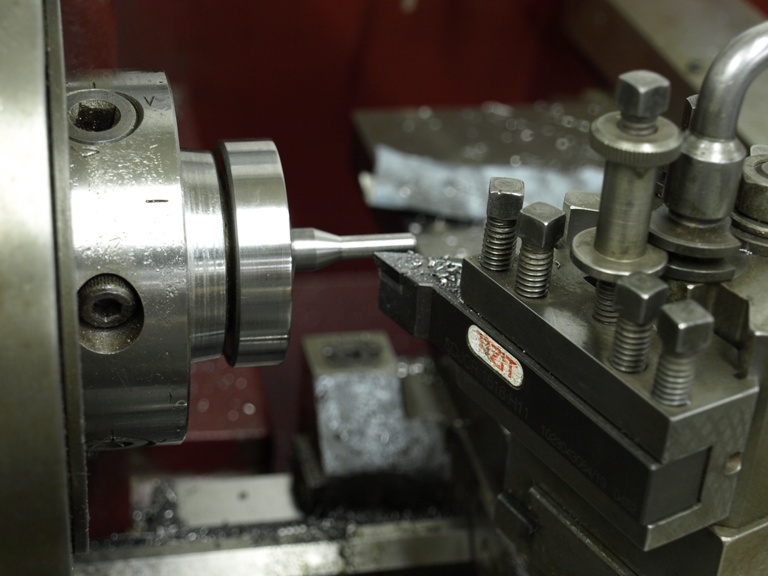
Blanks being turned for riser fixing screws.

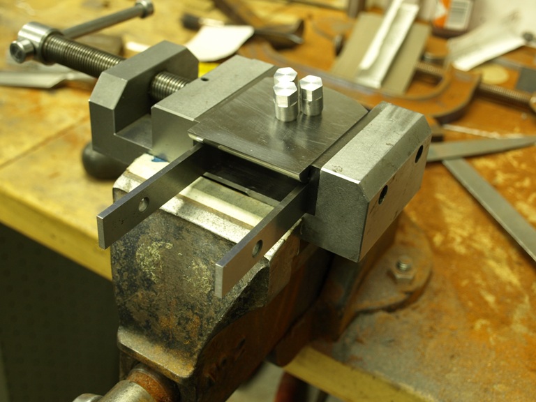
After threading the screws the bun riser is fixed to the bottom (on the underside in this picture, you can only see the three screws). Note the small machine vice, this is to hold the front bottom section for cutting off the screw heads – as is shown in the next picture.

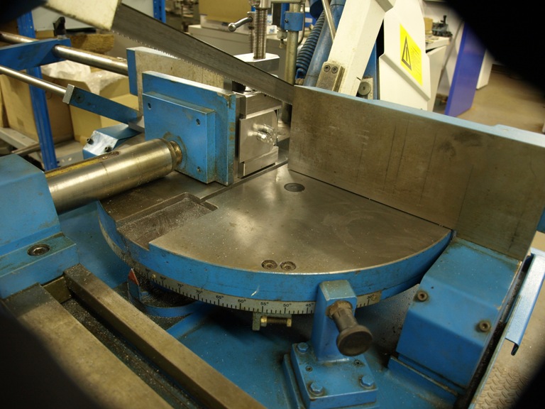
With the components secured in the small machine vice it is clamped on to the sawing table for trimming the screw heads.

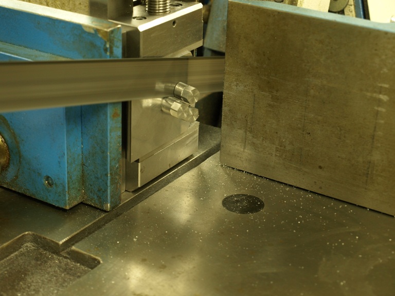
Going

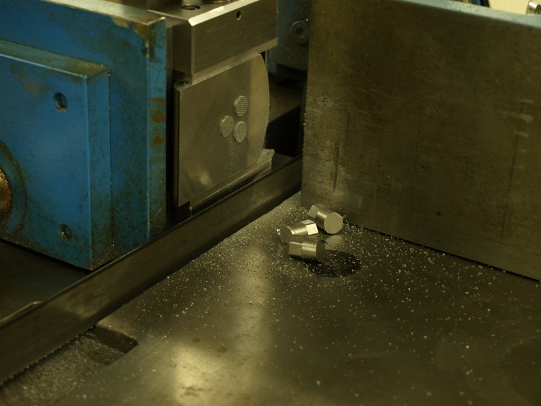
Gone. I hope I remembered the locking compound !

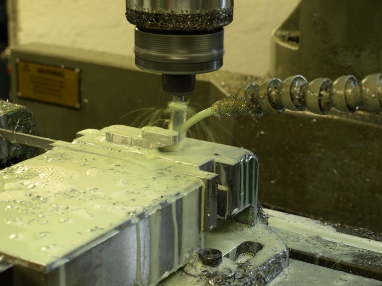
The protruding screws heads for the rear handle riser being milled away.

Window to my Workshop 22

Filed under: No 982 Smoother plane,Window to my Workshop — Tags: , , , — admin @ 5:33 pm

No 982 smoothing plane in the making - 4

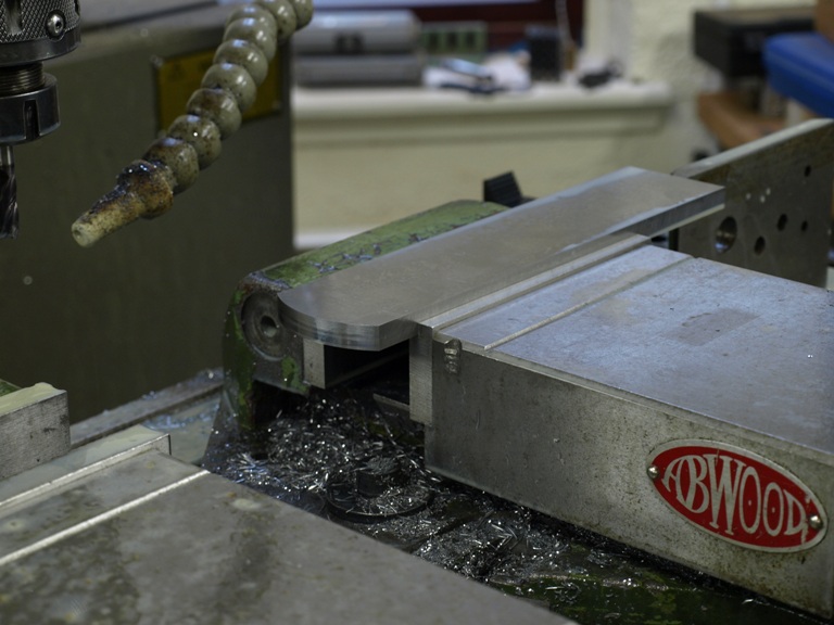
Now cutting the bottoms to separate the back end from the front – otherwise I will have the tightest mouth in the world. Actually the whole sole is made in one piece for the ease of matching.

Milling the blade bed after the separation on the bottom.

Now grinding the blade bed for precision.

The front end of the bottom having a radius form milled in front of the plane mouth for openness and better escape for the shavings – due to the extra thick bottom.

Boring the three fixing holes for the front bun riser (notice that the front bun is set at 15 deg from perpendicular).

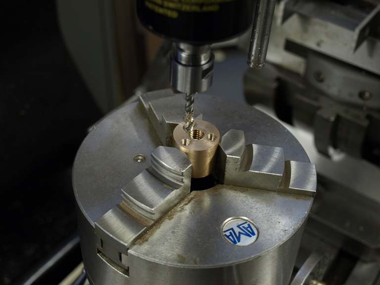
Drilling the three holes in the front bun riser for fixing screws. This one is in brass but then I decided to substitute with steel.

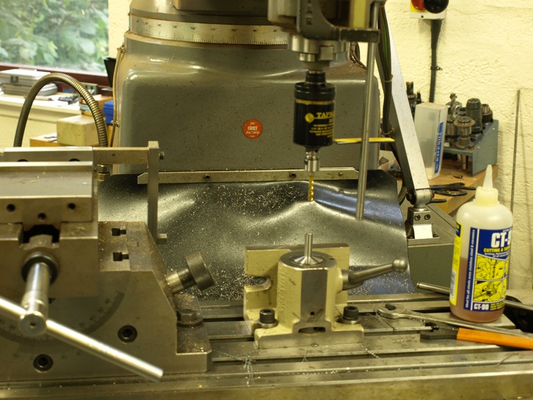
Tapping the three holes in the front bun riser.

More jig making. This is a carrier to hold the front riser for milling the 15 deg angle.

The carrier is ready for bolting down.

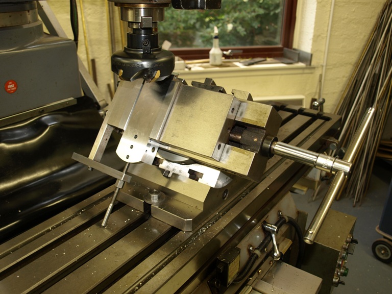
Setting the carrier up on the swivel vice for its 15 deg cut to the riser face.

As you can see the bun riser is firmly secured from underneath its riser with the three bolts, whilst the 15 deg angle is planed across its face.

The following two pictures would have been better in the last posting:

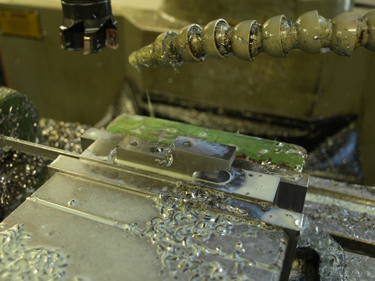
This is the lever cap bridge in silver steel being tapped after drilling.

The boring is done on the lathe, but this is a temporary set up for tapping.

Window to my Workshop 21

Filed under: No 982 Smoother plane,Window to my Workshop — Tags: , , , — admin @ 5:11 pm

No 982 smoothing plane in the making – 3

Lever caps

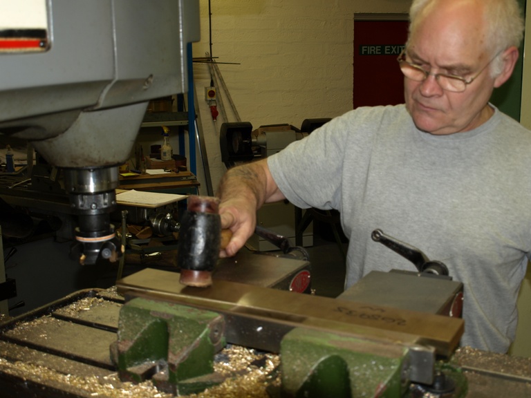
Tamping down lever cap bar (CZ112) for surfacing the lever caps in the mill before cutting them up individually.

(more…)

Window to my Workshop 17

Filed under: No 982 Smoother plane,Window to my Workshop — Tags: , , , — admin @ 4:29 pm

No 982 smoothing plane in the making – 1

After much deliberation over the design for nearly 12 months the work on the No 982 smoothing plane finally commenced in July 2008.

Most of my planes have been a combination of precision engineering and hand work which I look upon as a considerable upgrade on the original counterparts. In the case of the No 982 plane it would be very difficult to proceed without the precision machining. However, there is always plenty of work which is done by hand and has no substitute.

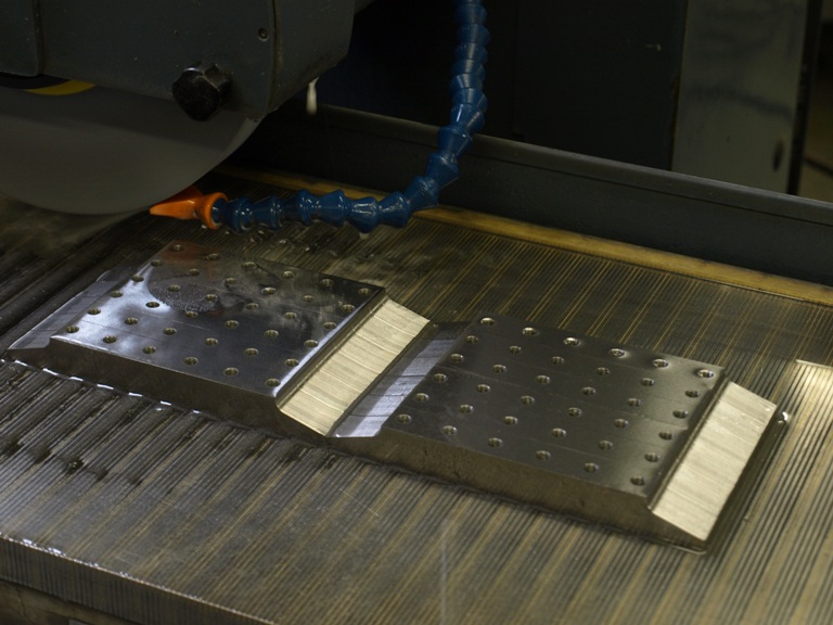
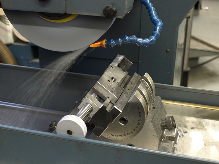
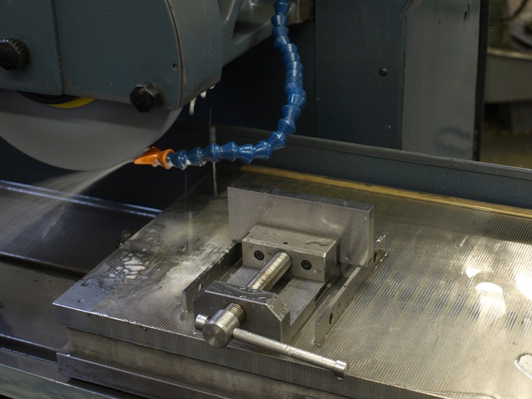
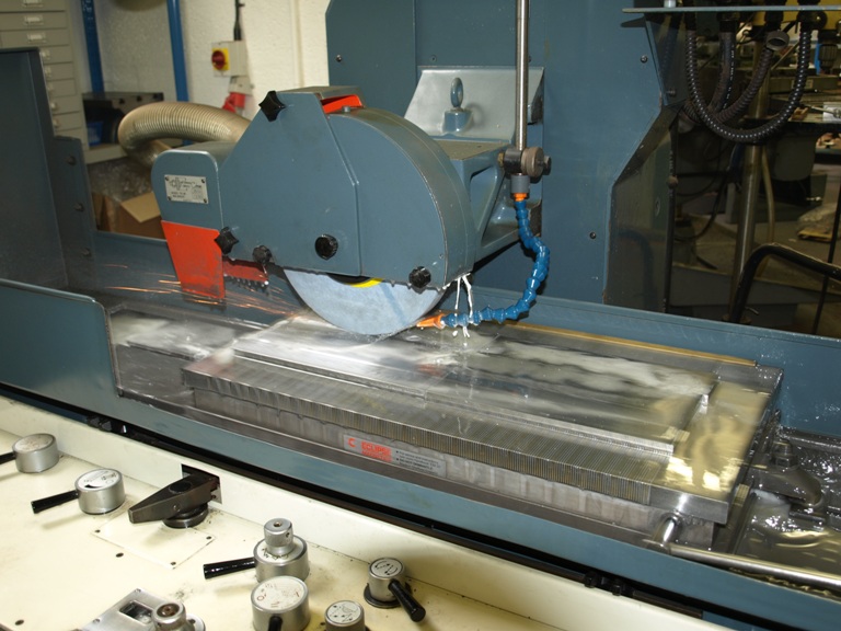
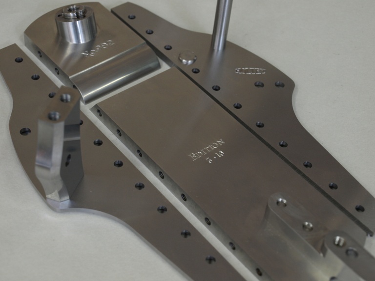
Those working with wood will know all the raw components need to be squared and straightened up before starting and this is the same with metal work. This is the bottom being ground after milling from a black bar.

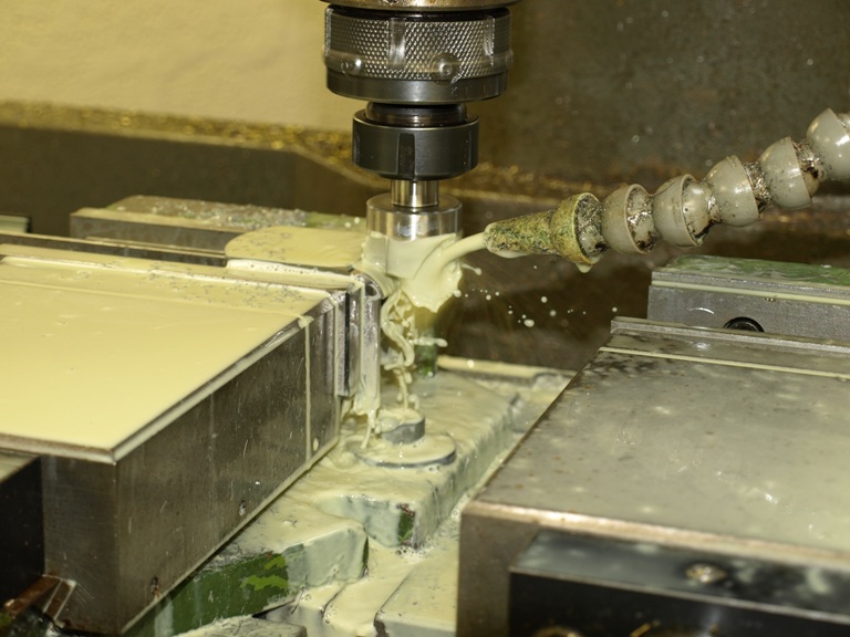
With the bottom faces being ground these bottoms will be nice and flat and parallel. At this stage I mill the edges on both sides to ensure that these are also square and parallel to each other, and also uniform.

Here you can see that I round the backs and fronts of the bottoms.

The rounding complete on the bottoms.

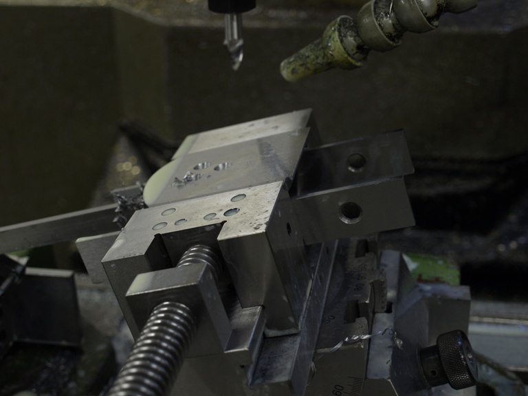
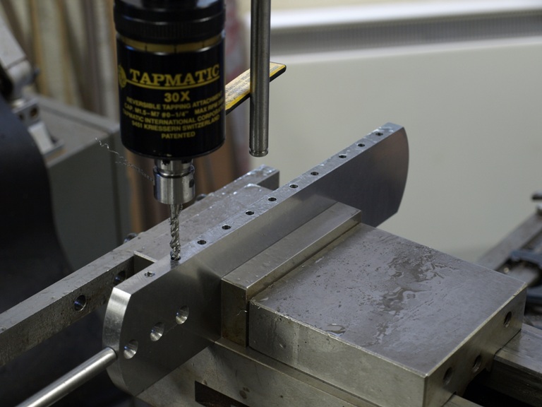
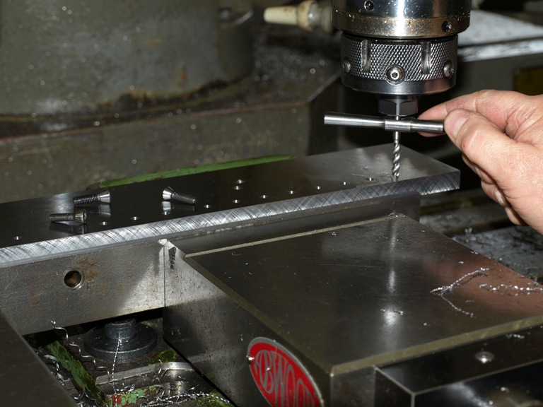
Drilling bottoms prior to tapping for the side fixing screws.

This is a different process from my usual dovetailing. It is also different from the rivets which I milled in situ for the No 98 smoothing and panel planes.
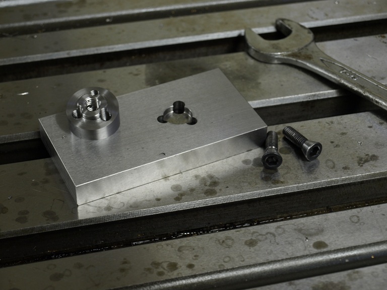
With riveting or dovetailing there is some movement and distortion which is very difficult to avoid. After some experimenting I found the screwing or bolting process is more reliable with no detectable movement. The sides and the bottoms remain perpendicular.

Tapping process for the screw holes.
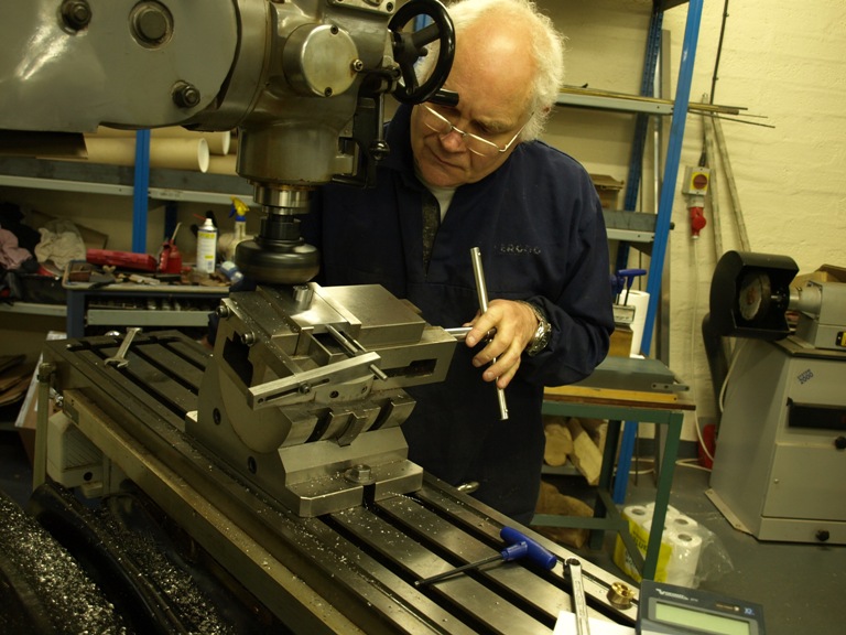
Drilling the fixing holes on the sides to take the new fixing system. The sides having already been prepared by milling and grinding.

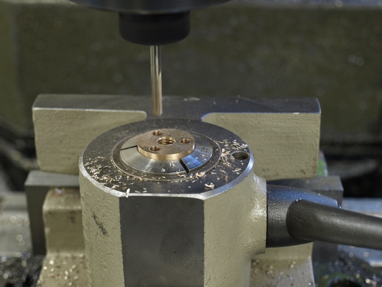
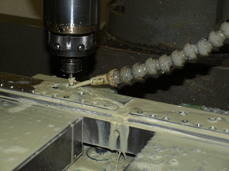
Counter boring the holes for fixing. These have a small taper and the holes are milled by CNC with a specially made undersized cutter for a better finish, not bored because boring would chatter and cause flats. The holes will match the tapered head of the screws.
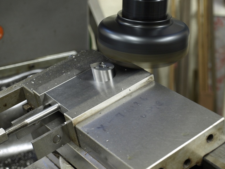
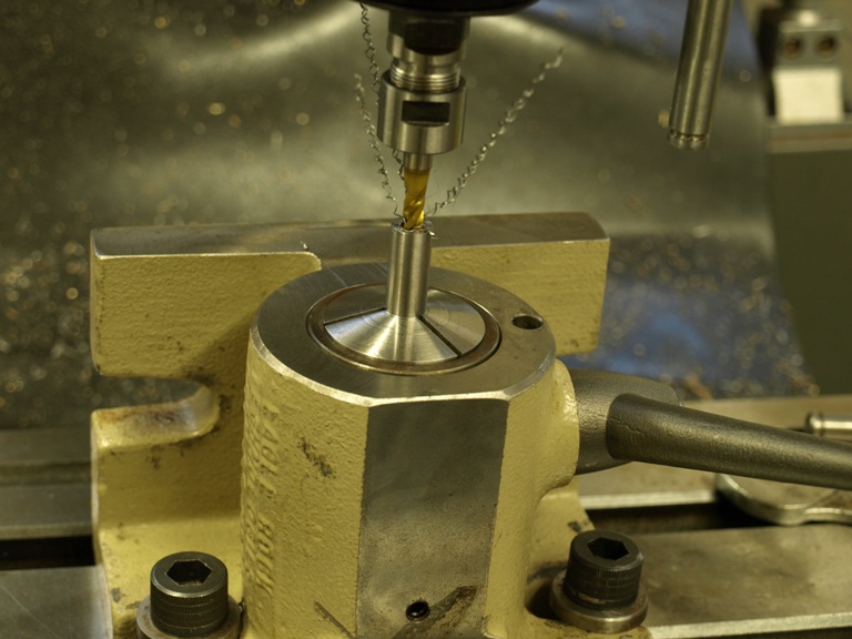
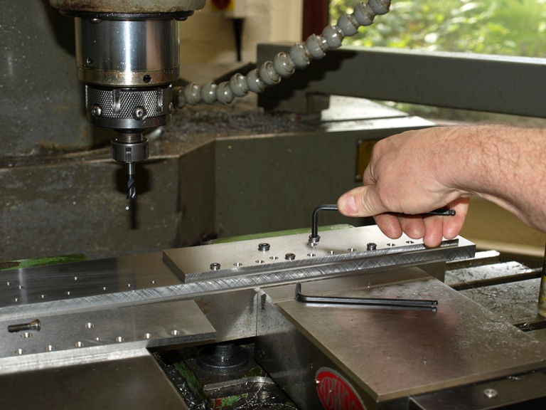
This shows the work holding plate for the sides being tapped after drilling. Then I am able to screw the sides down for routering and bevelling the side profile. The holding screws have been adapted to fit the tapers in the bore.

Screwing the sides to the work holding jig for routering.

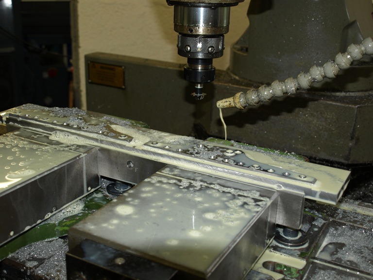
Routering out the sides

After routering and bevelling the sides. This leaves the sides ready for hand polishing the edges and bevel. There is also a small blade kicker to be rivetted in place.

Preview of next posting

Filed under: Previews — Tags: , — admin @ 11:07 am

The next posting will be on my A13 for the benefit of my customers waiting delivery of these planes. After that I want to start going through the making of the No 982.

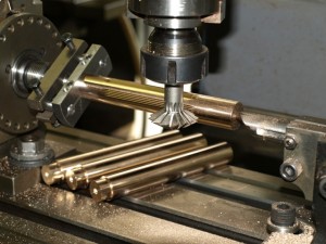
fluting the thumbs screw
Preview of the No 982 indexing thumb scew heads.

Powered by WordPress