Karl Holtey – Blog Archive

February 20, 2012

Window to my Workshop 25

Spiers Style Shoulder plane – 1

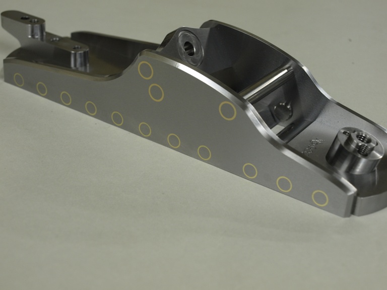
It seems appropriate to start this blog whilst I have a picture of these planes on my website home page here.

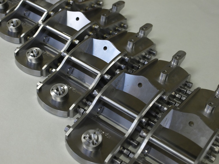
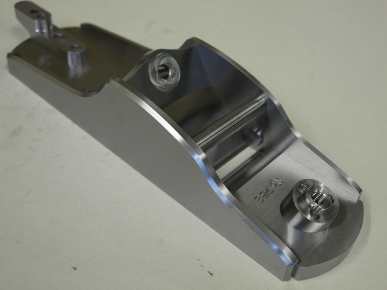
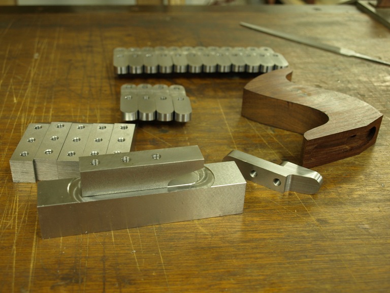
I don’t see myself making any more shoulder planes for some time. This style of plane is the only Spiers plane that appeals to me; in fact it is probably my favourite shoulder plane. The construction with its components is very much like the Norris A7 but has the shape I prefer. In the making of the Spiers I have had to make a lot of new tooling – for just six planes. As you follow this blog you will see some of my hidden work.

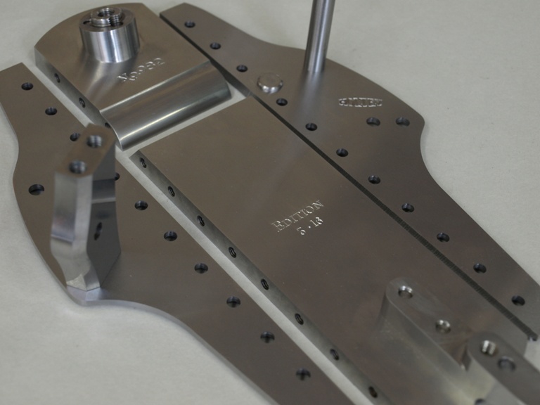
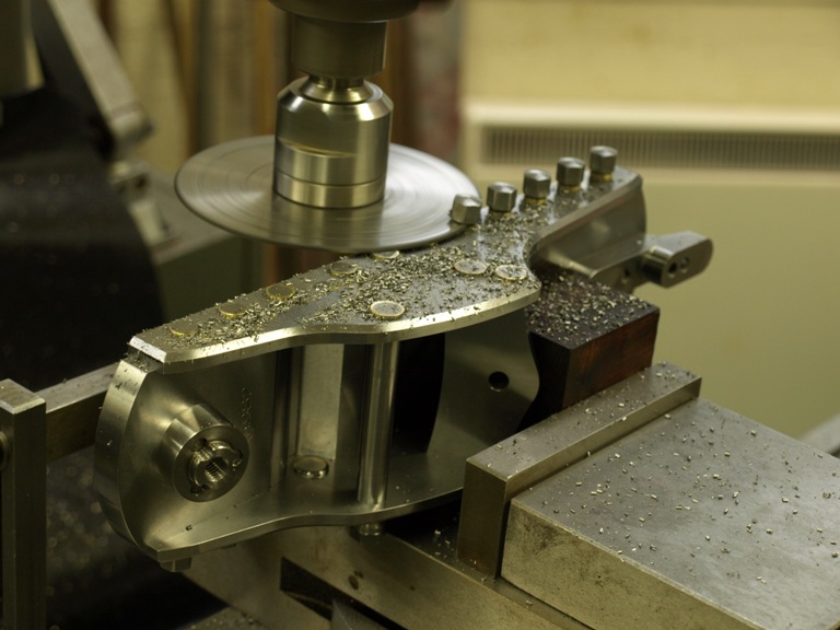
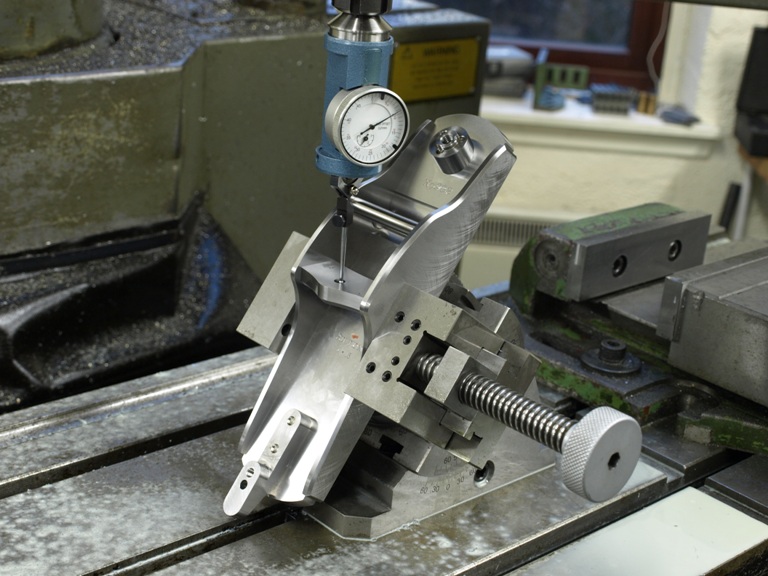
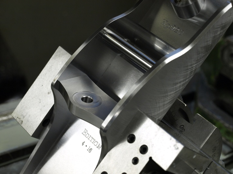
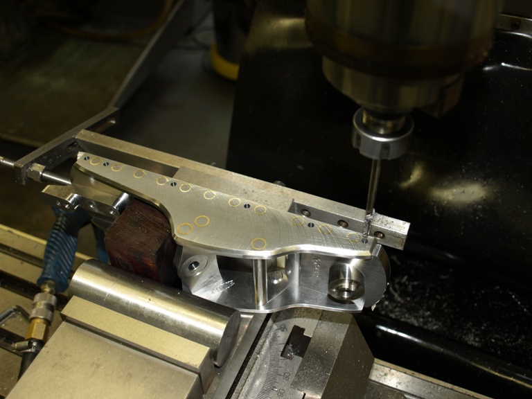
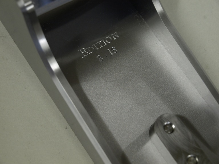
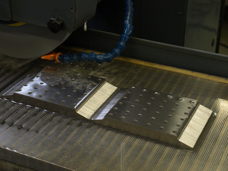
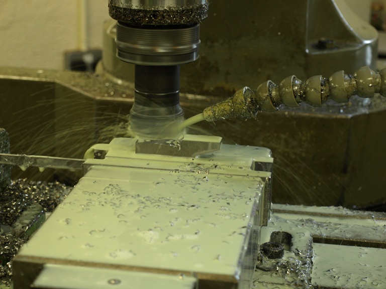
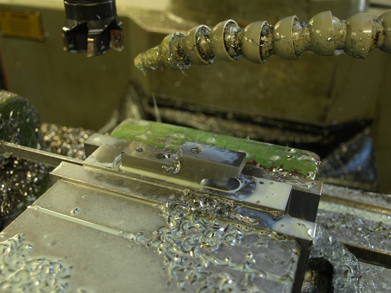
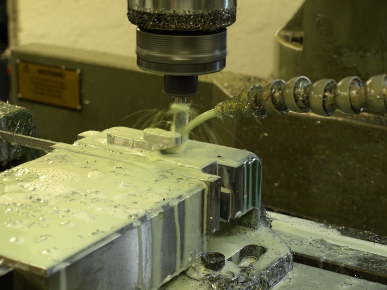
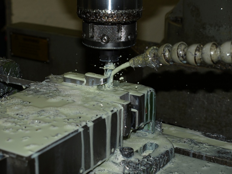
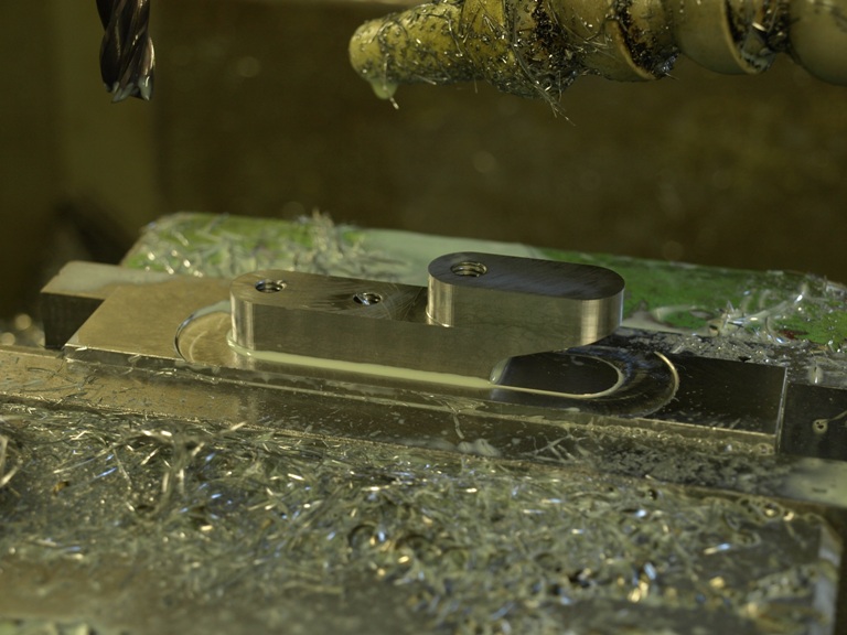
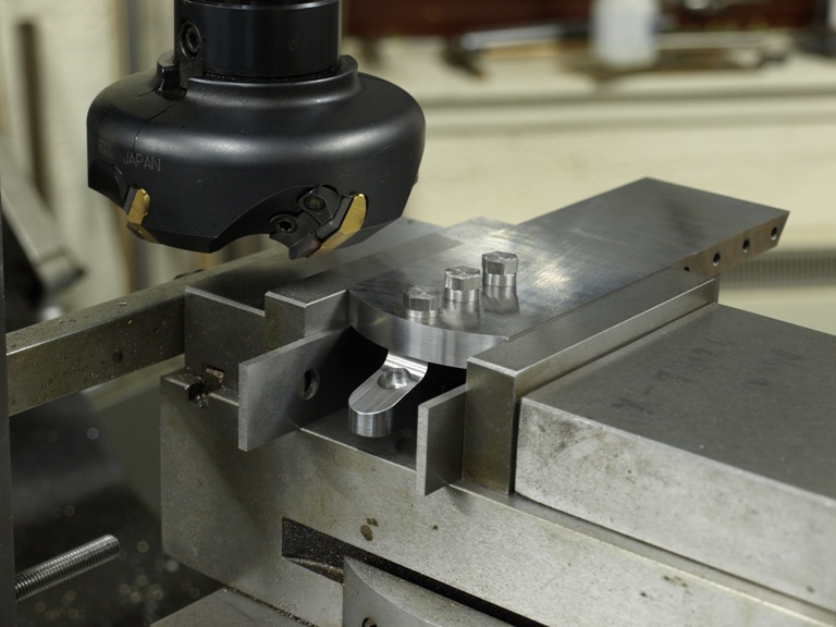
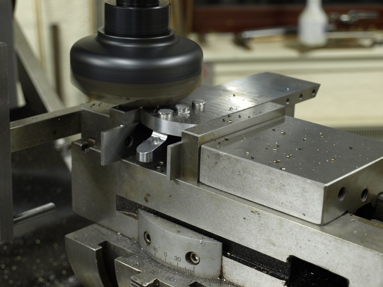
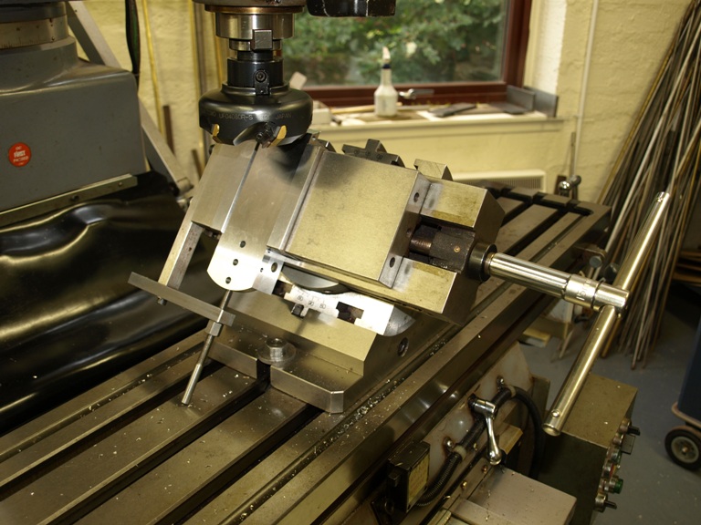
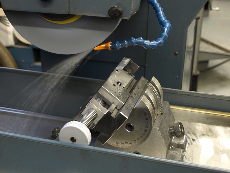
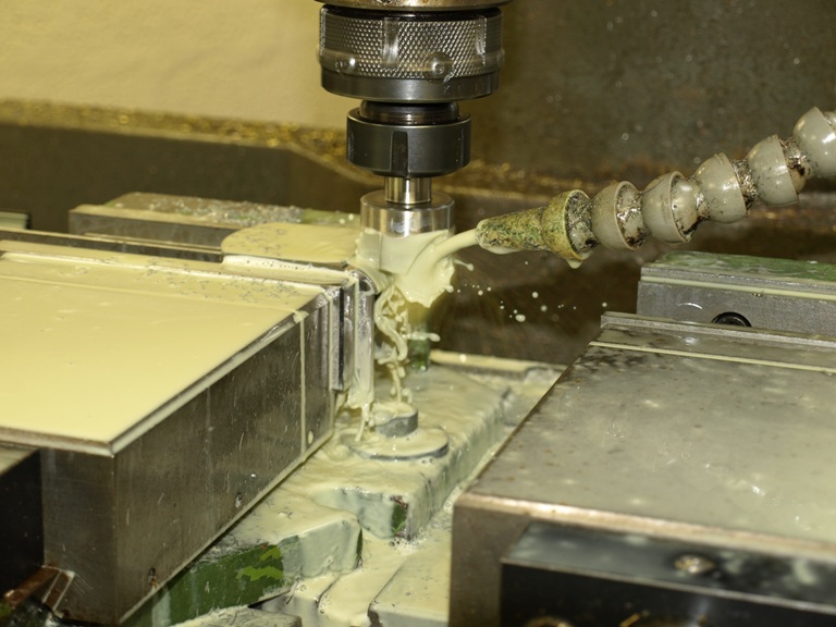
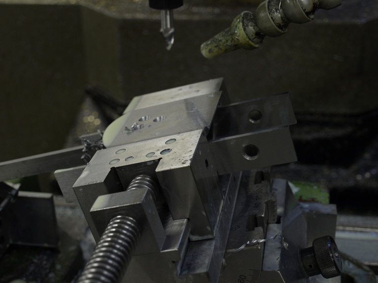
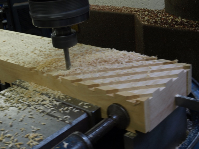
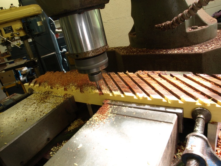
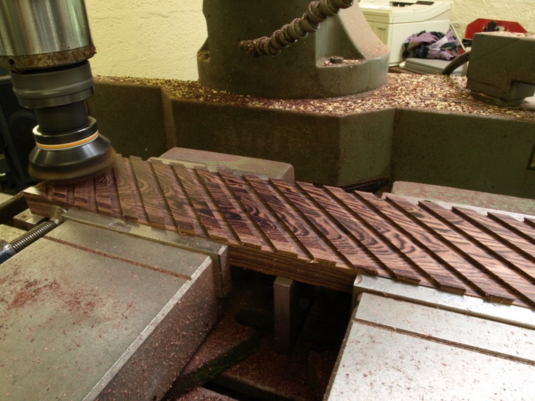
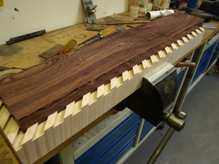
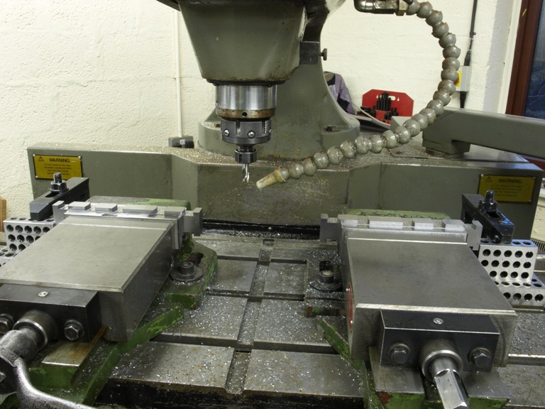
The following pictures show my familiar dovetailing of the bottoms being milled in pairs back to back so that I can form a compound dovetail. Please note that all the bottom blanks have been cut and precisionally ground all round in one piece (not separated at the mouth) at this stage.

(more…)

Window to my Workshop 24

Filed under: No 982 Smoother plane,Window to my Workshop — Tags: , , , — admin @ 6:31 pm

No 982 smoothing plane in the making – 6

Picture shows bottom and sides ready for assembly. This is showing the blade kickers riveted in place, both handle risers already fixed and both bridges in place. Note that the blade kickers hold the blade central whilst lateral adjustment is being applied to the blade.

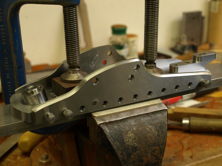
Sides now being fixed into place. Note the bottom is clamped to a bar during this process. This helps a lot in keeping things straight whilst the screws are given a final tightened up.

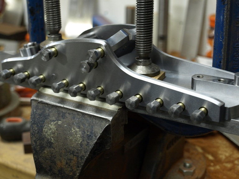
This picture shows the plane with the brass cones. The cones have not been tightened yet

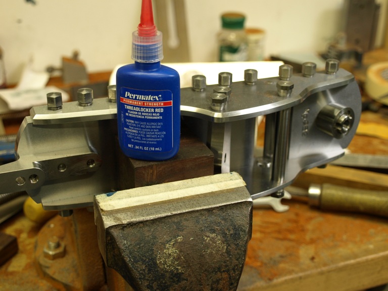
Showing the plane with all the screws tightened down. Now each screw is taken out one at a time, the locking compound applied and the screw retightened to its full torque.

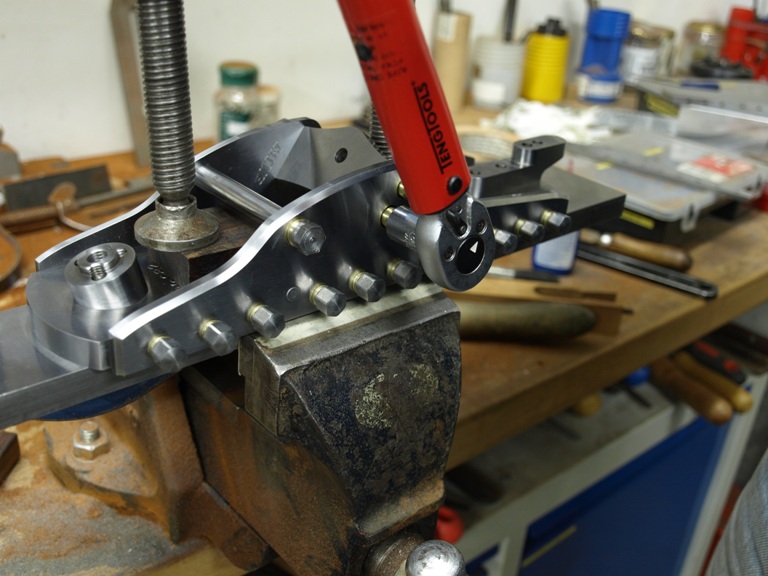
Torque wrench in use.

The planes starting to come together.

The bolts are now being chopped off with the slitting saw prior to milling and grinding

With the sides milled flush the adjuster bridge/bed can be reamed and then a shallow recess is milled in circular contour to make a bed for the adjuster. This is all done on exactly the same plane as the blade frog – as can be seen in the next picture.

Showing the recess around the adjuster bore forming a true bed for the adjuster.

Though all the fixing appears to be complete there is still the drilling and reaming for the taper pins to go into their 6 positions. This maintains a positive lock between the bottom and the sides, as seen on the picture. The reason for this is just a bit of extra insurance against any movement caused by impact.

Picture showing the internal grinding texture which is a pleasant by-product of all the grinding and truing up at the beginning of the project.

Body without the cones

Body with the cones.

Window to my Workshop 23

Filed under: No 982 Smoother plane,Window to my Workshop — Tags: , , , — admin @ 5:53 pm

No 982 smoothing plane in the making - 5

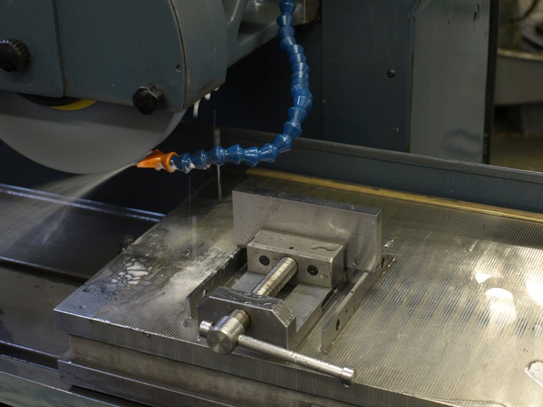
There are 24 handle risers being ground true. Made in pairs joined end to end for ease of working.

The handle riser having been parted from its partner is now having its step milled into it.

With the step now formed ready for the radiuses

The radiuses being rough cut

The radiuses now with the finishing cut (three radiuses in total).

Handle riser now complete.

Showing pre-worked handle risers with one on its machining carrier and one rosewood handle just about showing its riser recess.

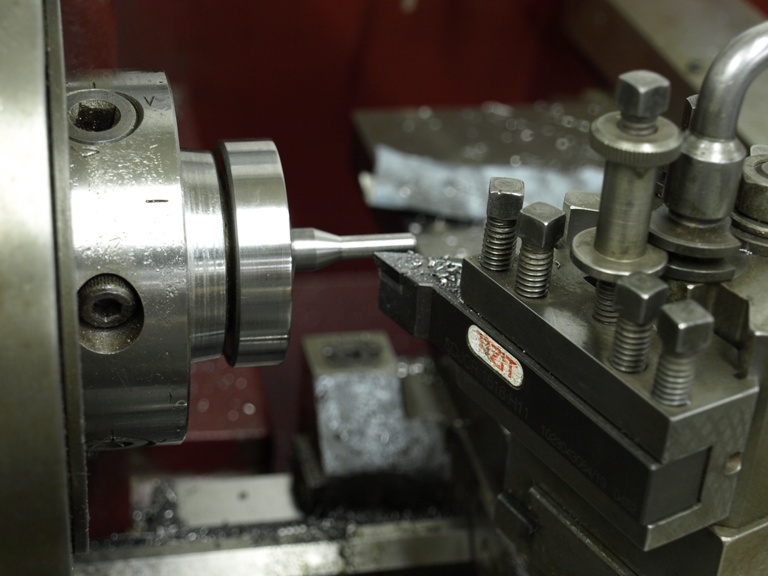
Blanks being turned for riser fixing screws.

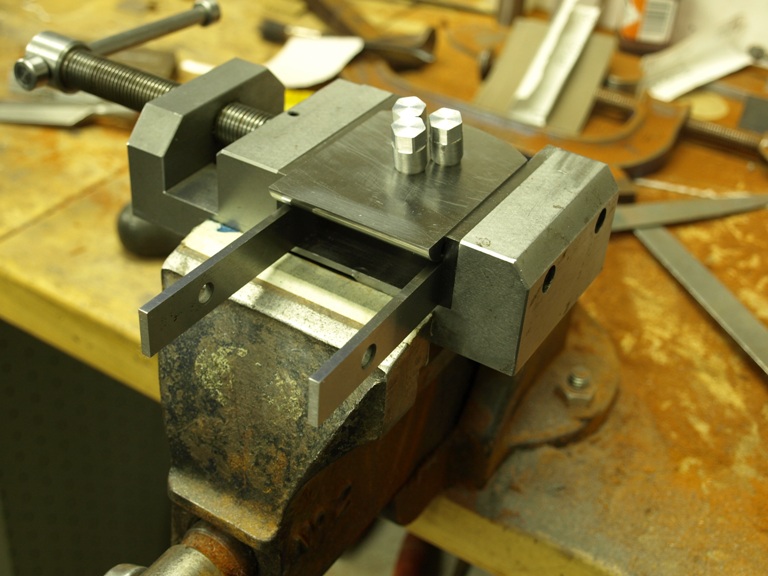
After threading the screws the bun riser is fixed to the bottom (on the underside in this picture, you can only see the three screws). Note the small machine vice, this is to hold the front bottom section for cutting off the screw heads – as is shown in the next picture.

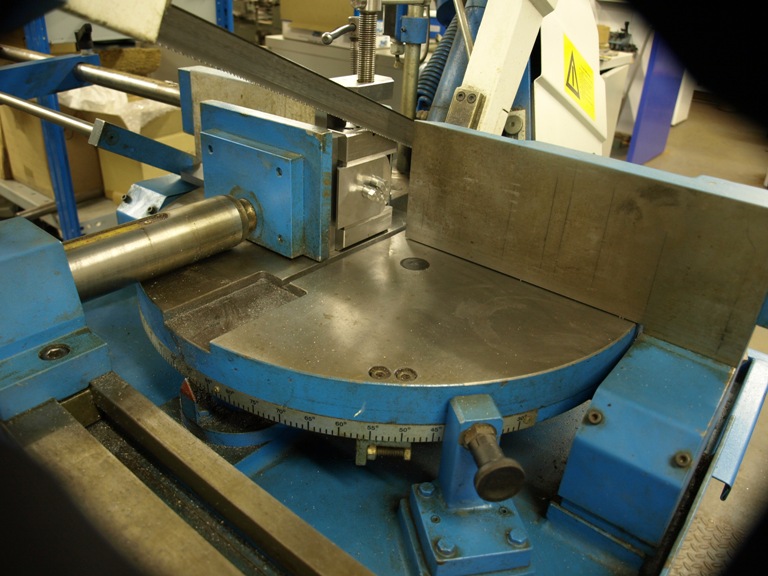
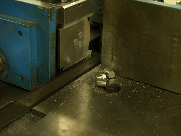
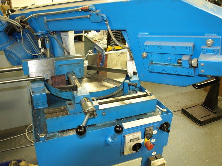
With the components secured in the small machine vice it is clamped on to the sawing table for trimming the screw heads.

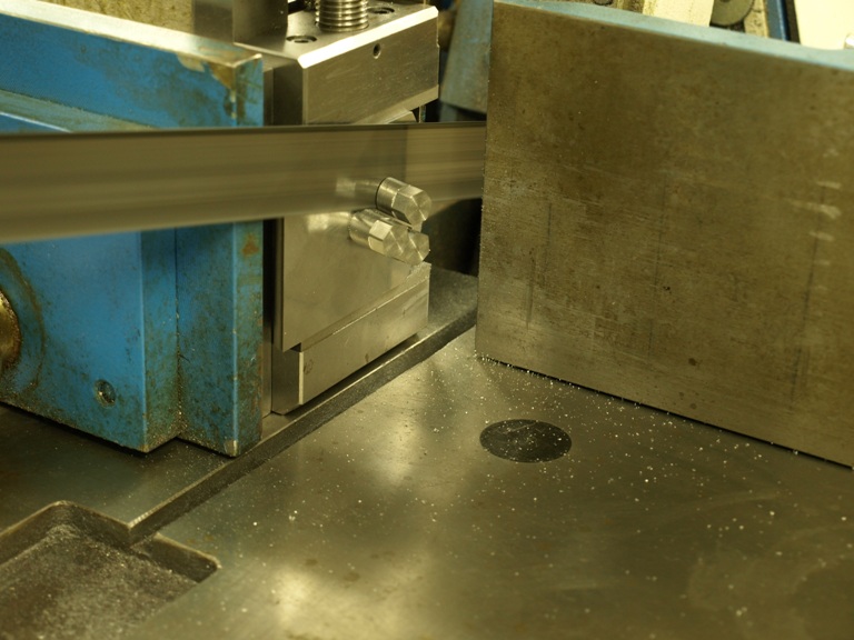
Going

Gone. I hope I remembered the locking compound !

The protruding screws heads for the rear handle riser being milled away.

Window to my Workshop 22

Filed under: No 982 Smoother plane,Window to my Workshop — Tags: , , , — admin @ 5:33 pm

No 982 smoothing plane in the making - 4

Now cutting the bottoms to separate the back end from the front – otherwise I will have the tightest mouth in the world. Actually the whole sole is made in one piece for the ease of matching.

Milling the blade bed after the separation on the bottom.

Now grinding the blade bed for precision.

The front end of the bottom having a radius form milled in front of the plane mouth for openness and better escape for the shavings – due to the extra thick bottom.

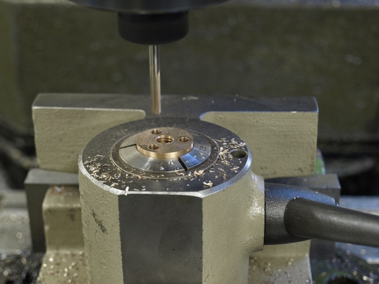
Boring the three fixing holes for the front bun riser (notice that the front bun is set at 15 deg from perpendicular).

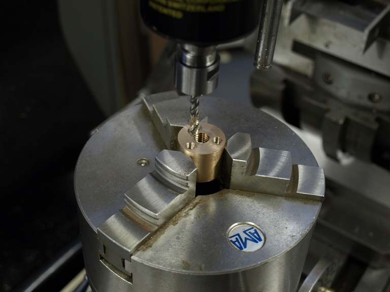
Drilling the three holes in the front bun riser for fixing screws. This one is in brass but then I decided to substitute with steel.

Tapping the three holes in the front bun riser.

More jig making. This is a carrier to hold the front riser for milling the 15 deg angle.

The carrier is ready for bolting down.

Setting the carrier up on the swivel vice for its 15 deg cut to the riser face.

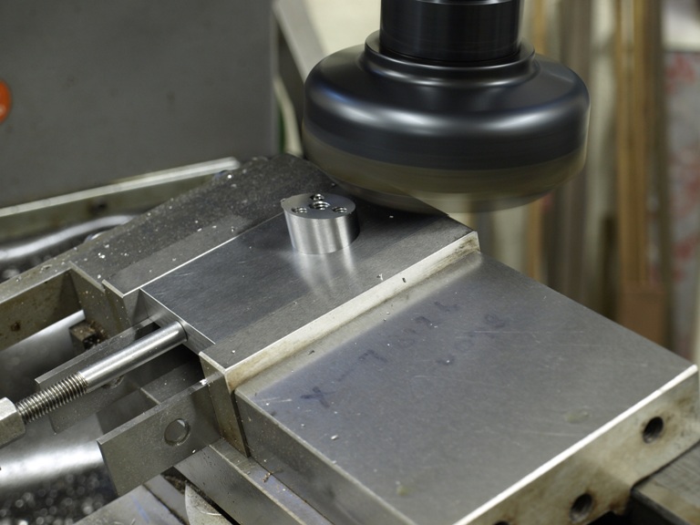
As you can see the bun riser is firmly secured from underneath its riser with the three bolts, whilst the 15 deg angle is planed across its face.

The following two pictures would have been better in the last posting:

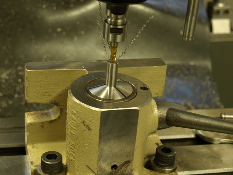
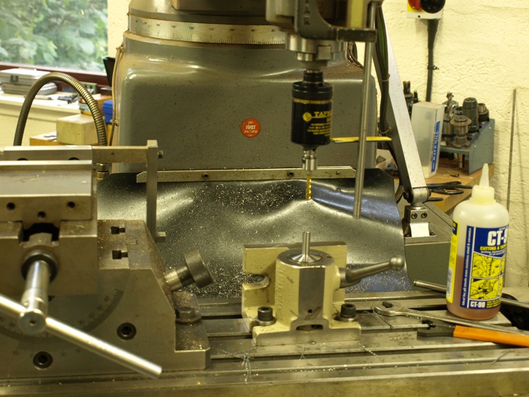
This is the lever cap bridge in silver steel being tapped after drilling.

The boring is done on the lathe, but this is a temporary set up for tapping.

Window to my Workshop 21

Filed under: No 982 Smoother plane,Window to my Workshop — Tags: , , , — admin @ 5:11 pm

No 982 smoothing plane in the making – 3

Lever caps

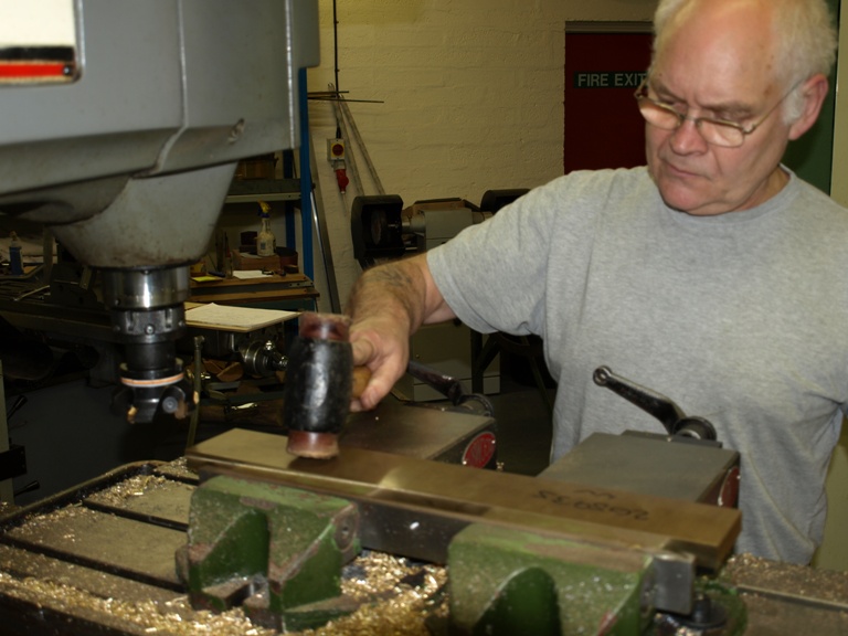
Tamping down lever cap bar (CZ112) for surfacing the lever caps in the mill before cutting them up individually.

(more…)

Window to my Workshop 20

No 982 smoothing plane in the making -2

Here is the making of the thumb screws.

It is only just a few shots taken at random so there are a lot of steps missed out.

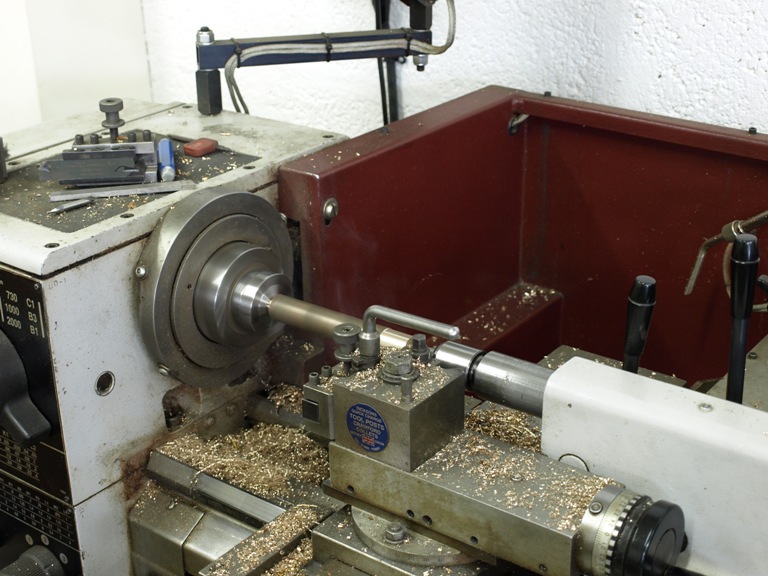
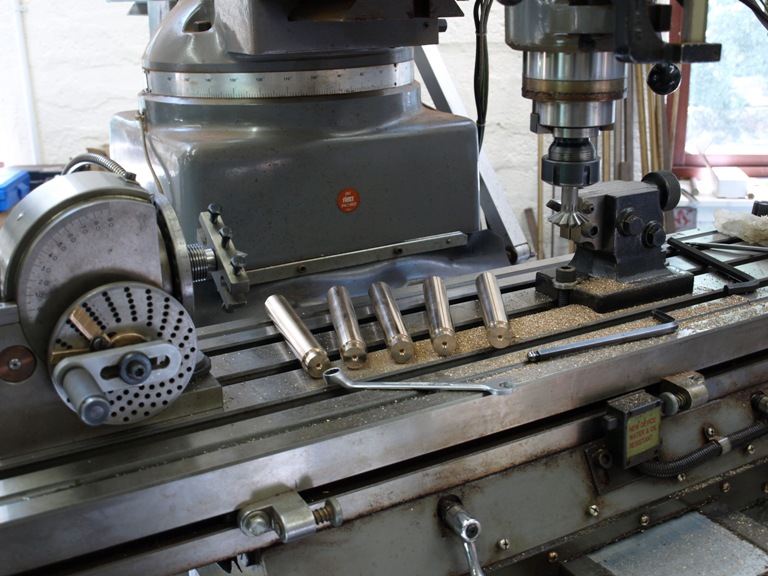
Truing up an extruded gun metal bar on the lathe, for thumb screws and adjuster knobs. i.e. each bar cuts two thumb screws and two adjuster knobs.

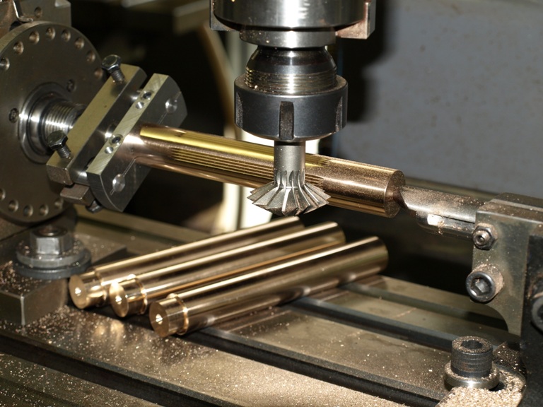
These are the gun metal blanks after truing up and adding centres on the ends for work holding. The dividing head and tail stock are ready – set up for knurling the blanks. This is a very costly and complicated way to produce a knurl, but for this knurling there is no way other than to index it on the milling machine.

The blanks are set up on the dividing head showing the driving dog and tail stock. This is to cut the V shape grooves which form the knurl. The dividing head is used to index the spacing to the required divisions.

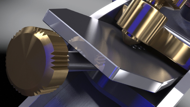
This computer generated image demonstrates the knurling design for this plane and helps explain why I need to use the above process.

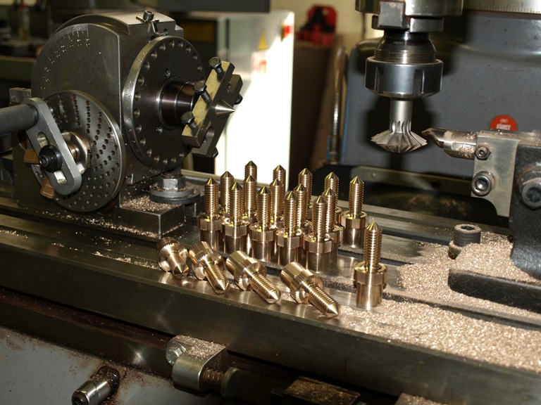
As you can see from this photograph on the milling table, all the indexing work is complete having been returned to the lathe for more turning and thread cutting. The components have also been parted. These are the thumb screws only, showing the carriers which are still to be parted off.

Window to my Workshop 19

Filed under: Transitional T21,Window to my Workshop — Tags: , , , — admin @ 4:44 pm

Holtey Transitional Jointer Plane – 2

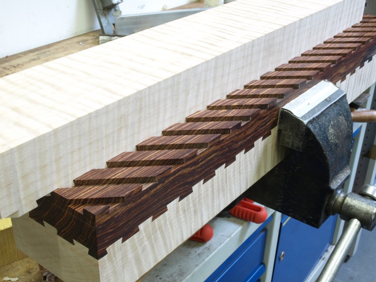
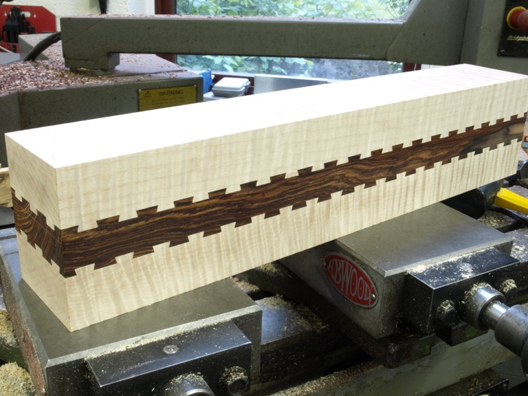
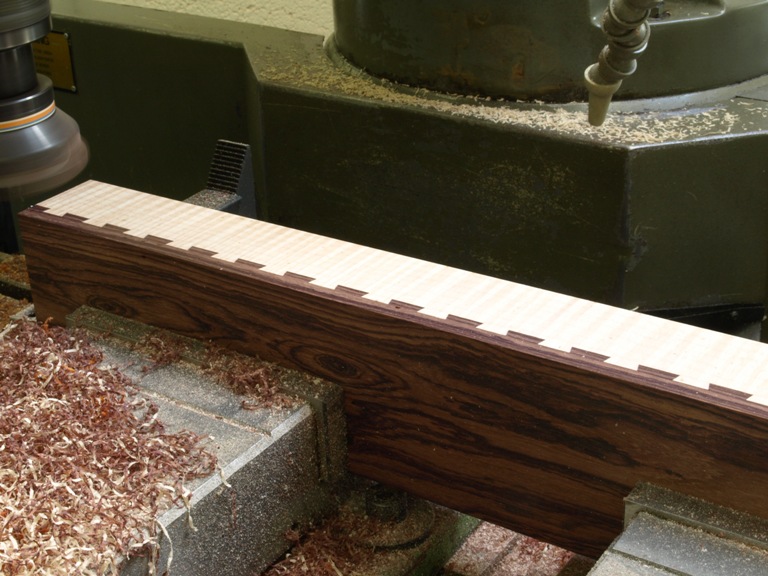
As there have been comments about this dovetailed jointing system I realised that I should show the pictures of the dovetailing in progress.

There are a few who know the dovetail puzzle of using a cube made up of two contrasting woods showing one dovetail on each side. In the case of a square object you cut the angle of 45 deg for the path of the dovetails (two) so that the joint slides into position with this angle, which gives an even sized dovetail on all four sides.

Once you start altering the dimensions and the number of dovetails then it becomes complicated. If it was not for my CNC it would be a nightmare.

The first cut for the dovetailing is done with a plain cutter so that I can reduce the mileage on the dovetail cutter.

With the grooving complete I can then follow through with the dovetail form cutter (tungsten carbide as on all my tools).

The depth of the dovetails has allowed for a final skim over the top to guarantee a uniform depth and also gives a neater finish.

The exciting stage – sliding the dovetails together.

You will notice that some of the bottoms are to be cut to make two bottoms after they have been jointed and glued on both sides.

This is two bottoms waiting to be glued. The gluing is not so much for adhesion but in this application it is mechanical. The only way to undo this joint is by sliding so once the glue has hardened it becomes keyed to the texture of the wood. The dovetailing is a quantum leap from tongue and grooving used by other manufacturers.

For the gluing I have used polyurethane with an open time of at least half an hour – well that is what they say on the tin. In real life the comfort time is less than 5 mins. So preparation and rehearsal is necessary. I use the polyurethane so that I don’t introduce any more moisture into the wood. Also it expands so taking up any voids. I have a loose fit of 8 thou so that the joints are reasonably easy to slide together and still have a small glue line.

It is extremely important that the gluing should be done soon after the dovetailing because wood is unstable and it can fit today and not tomorrow.

Window to my Workshop 18

Filed under: Transitional T21,Window to my Workshop — Tags: , , , , — admin @ 4:37 pm

Holtey Transitional Plane

For some time I have had a fascination for transitional planes. Since I have made two planes that are mainly made from metal it seems fitting that I should now make a transitional plane.

The designs that have had the greatest influence on me are John Gage’s planes, but of course I feel the need to upgrade on the metal working side. I like the lightweight and low profiles of these planes and believe they could find favour with quite a few people.

I also have some interest in ECE Primus planes but again I don’t like their metal work. I do, however, like the laminated sole very much. I feel I could improve here by dovetailing the hardwood sole instead of grooving. It will be technically superior as the mechanics of this jointing system is not totally dependent on glue.

There are some problems in the making of this dovetailed system but I have overcome them with a considerable amount of thought and work. I will be very dependent on the use of my CNC machine. It could provide quite a challenge for the home constructor.

As you may have noticed from a previous post I have already jointed and glued the bodies and they have been settling in my workshop for the past three months.

The timber that I am using is Quilted Maple, for its beautiful figure and light weight. I have a choice of two different woods for the sole; one is a Cocobolo rosewood (Dalbergia retusa) for its density and oiliness, or the Guatemalan Rosewood (Dalbergia cubiquitzensis) which is also dense and oily.

Though I have had considerable interest in these planes I am not taking orders until I can price them.

The picture shows the plane body being flushed using a face cutter in the milling machine. This is not just the only practical way of planing this very difficult wood because of the character of its grain, but I am also applying a high degree of precision.
(more…)

Window to my Workshop 17

Filed under: No 982 Smoother plane,Window to my Workshop — Tags: , , , — admin @ 4:29 pm

No 982 smoothing plane in the making – 1

After much deliberation over the design for nearly 12 months the work on the No 982 smoothing plane finally commenced in July 2008.

Most of my planes have been a combination of precision engineering and hand work which I look upon as a considerable upgrade on the original counterparts. In the case of the No 982 plane it would be very difficult to proceed without the precision machining. However, there is always plenty of work which is done by hand and has no substitute.
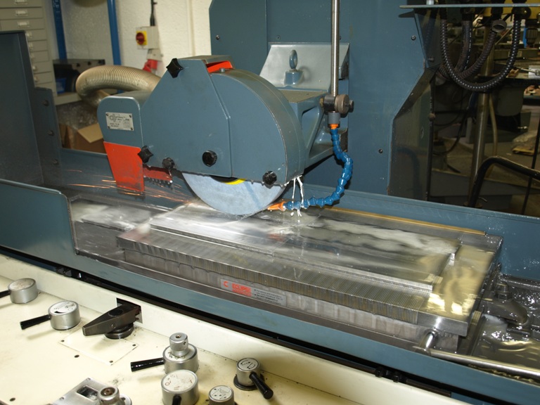
Those working with wood will know all the raw components need to be squared and straightened up before starting and this is the same with metal work. This is the bottom being ground after milling from a black bar.
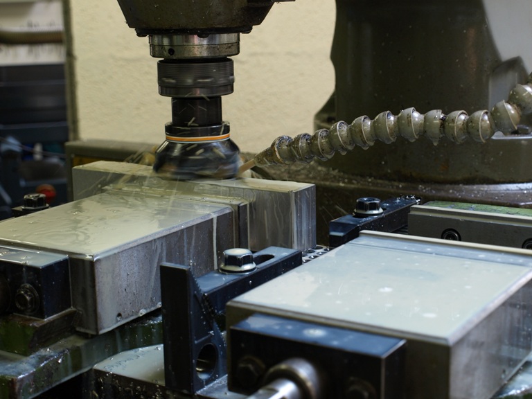
With the bottom faces being ground these bottoms will be nice and flat and parallel. At this stage I mill the edges on both sides to ensure that these are also square and parallel to each other, and also uniform.
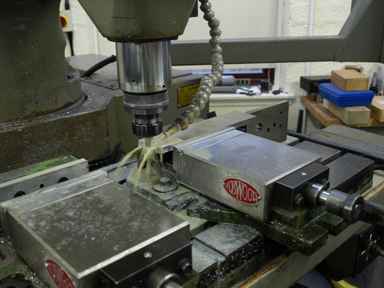
Here you can see that I round the backs and fronts of the bottoms.
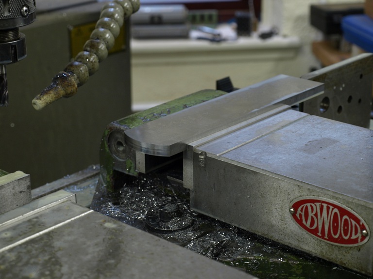
The rounding complete on the bottoms.
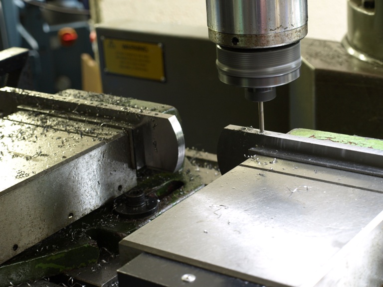
Drilling bottoms prior to tapping for the side fixing screws.

This is a different process from my usual dovetailing. It is also different from the rivets which I milled in situ for the No 98 smoothing and panel planes.

With riveting or dovetailing there is some movement and distortion which is very difficult to avoid. After some experimenting I found the screwing or bolting process is more reliable with no detectable movement. The sides and the bottoms remain perpendicular.
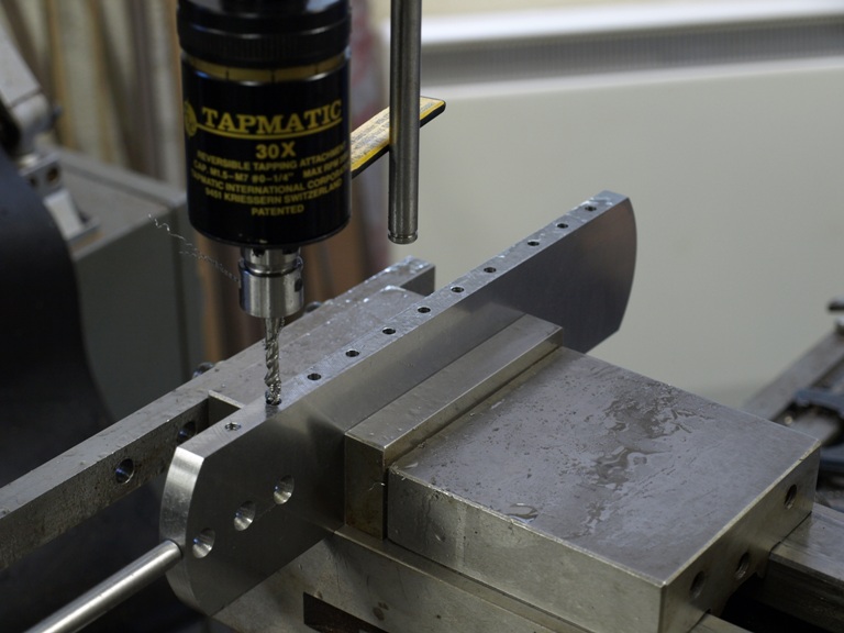
Tapping process for the screw holes.
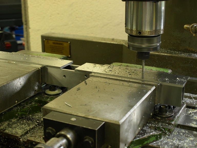
Drilling the fixing holes on the sides to take the new fixing system. The sides having already been prepared by milling and grinding.
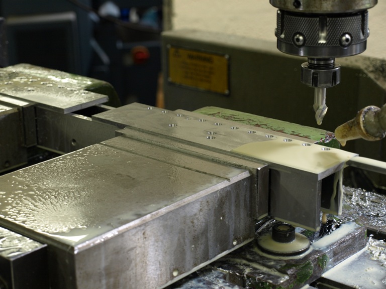
Counter boring the holes for fixing. These have a small taper and the holes are milled by CNC with a specially made undersized cutter for a better finish, not bored because boring would chatter and cause flats. The holes will match the tapered head of the screws.
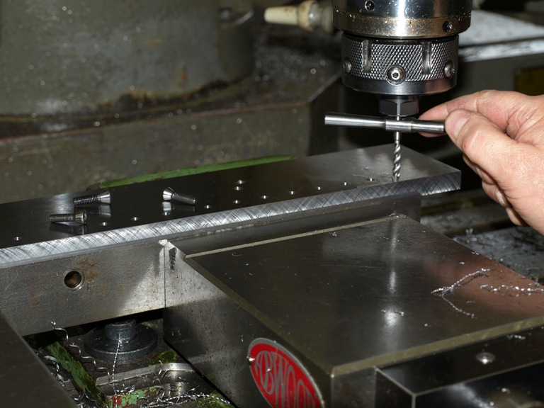
This shows the work holding plate for the sides being tapped after drilling. Then I am able to screw the sides down for routering and bevelling the side profile. The holding screws have been adapted to fit the tapers in the bore.
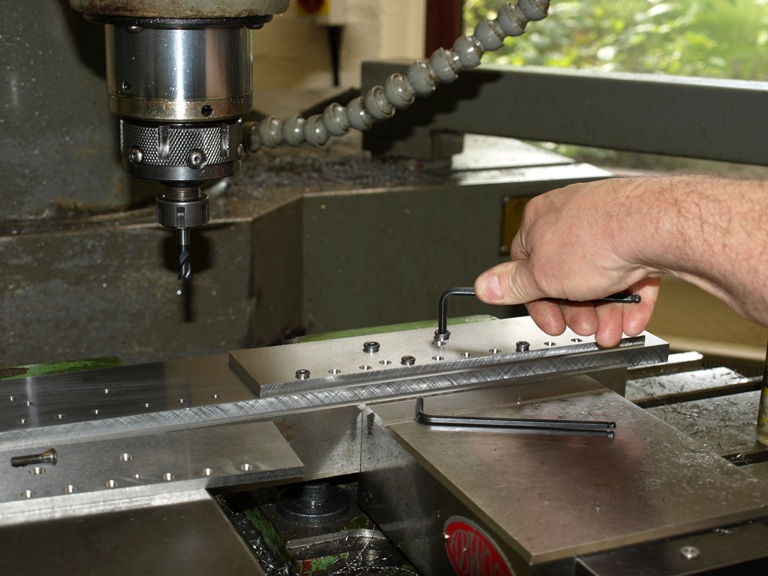
Screwing the sides to the work holding jig for routering.
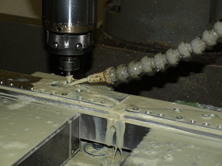
Routering out the sides
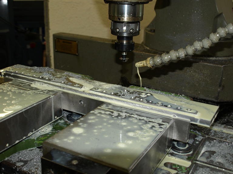
After routering and bevelling the sides. This leaves the sides ready for hand polishing the edges and bevel. There is also a small blade kicker to be rivetted in place.
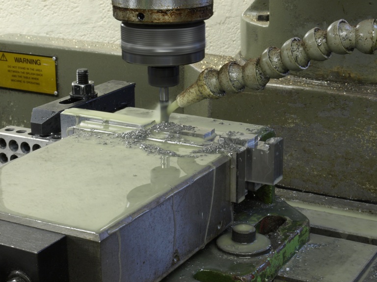
Window to my Workshop 16

Filed under: A13,Conclusion,Window to my Workshop — Tags: , , , — admin @ 3:45 pm

Conclusion of making the A13 dovetailed infill planes

For a long time I have procrastinated in writing a blog, and in that time I have kept a library of pictures of plane making throughout my range hoping to document it over time.
With the A13 I have tried to give some idea of the sheer effort that goes into the making. Although I have missed out much of the story, I hope it is enough to provide an overall picture. I have shown the mixture of hand and machine work that is necessary to achieve something of this quality. Also, I hope that I have shown that the machine work is not an economy but a necessity.
I decided to make the A13 because I could see potential in this design and its very appealing aesthetics, and it has turned out to be my best seller. From the blog you will see that a lot of detail has been upgraded. Some of the enhanced contours have been copied by others and referred to as an A13 when in actual fact it is a Holtey designed A13 and not a Norris. The original Norris A13 was cast iron which supported a square bun. However the introduction of dovetailing (mainly brass on steel) and riveting through metal spacers are all my ideas.

With the completion of these few planes, I feel that I want to move on and look for a replacement for this infill design.

Older Posts »

Powered by WordPress