Making of A13
Not quite all of the sequential process, but most of it – not necessarily in order
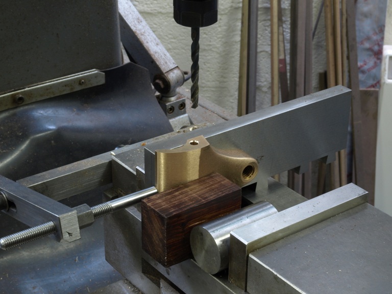
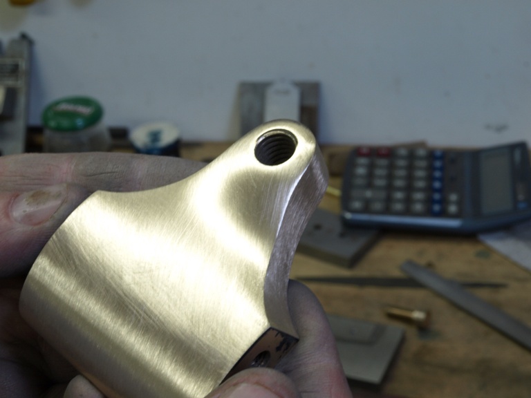
A13 drilling lever cap for pivot screw
All my drilling and tappings are done in the milling machine so that I can achieve the best positioning and concentricity.
This is my A13 lever cap. As it is going into a brass sided plane I am using my original machine screws instead of my removable lever cap system. These pivot screws are, as in everything else, made in house. This screw is of a cheese head type for positive bearing contact. I have seen some planes with countersunk screws here; this lacks understanding because if tight it will have a pinching effect on the plane sides and lock everything and you will impede the lever cap rotation. If it is not tightened it could allow the lever cap to float a bit. It must be positively stable with a good bearing contact, a cheese head screw has a flat underside to the head which tightens down on to the side of the lever cap. The head sides are parallel which meets the forces directly.
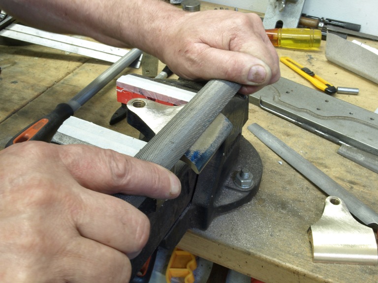
A13 draw filing lever cap
As some of you will know most sand castings are from perfect. The contours need truing up.
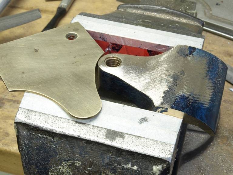
A13 lever cap filing
This photo shows the lever cap with a reference template which has the top and bottom contours either side of its centre line.
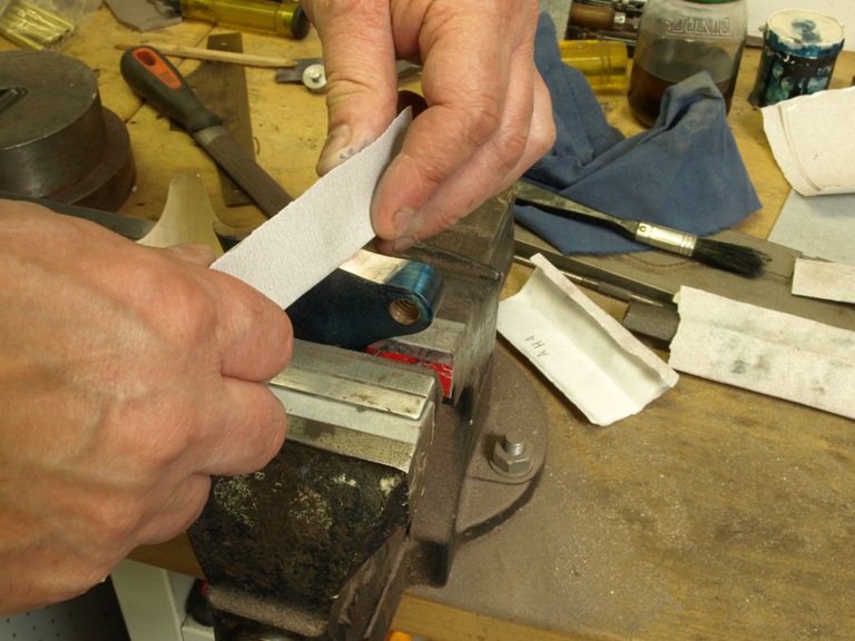
A13 lever cap edge polishing
A13 lever cap using light reflections
Using light reflections is the best reference for showing up errors in the compounding contours.
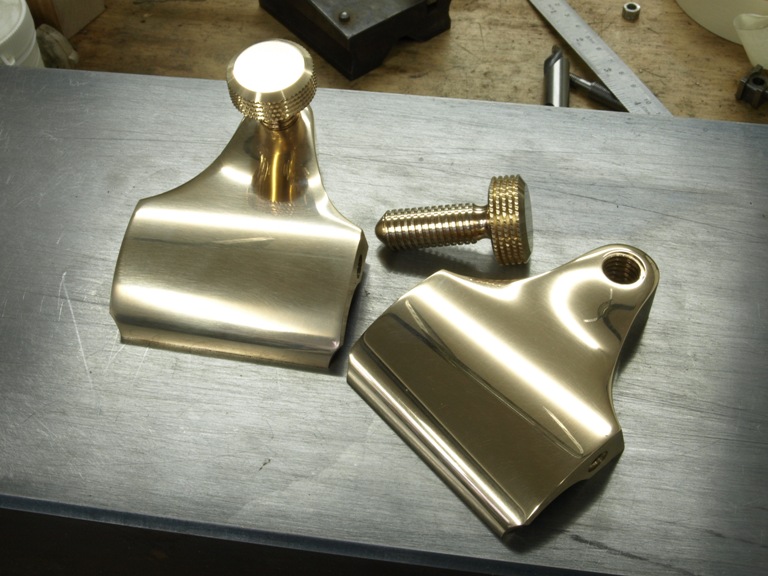
A13 finished lever caps
After much filing the polishing is done with an abrasive paper and graduated down to 1200 in 6 stages. Then the lever caps are lightly buffed and then polished with one of many metal polishes available. Any irregularities are shown up with this type of reflective finish.
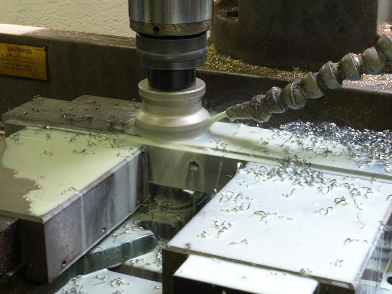
A13 bottom thicknessing
Often it is necessary to resize the raw materials. The mill does the job quite well as it also removes the scale.
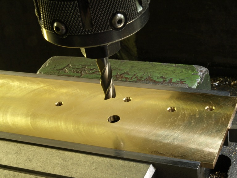
A13 side drilling
Sometimes I rely on the milling machine as a jig borer. As you can see all the holes are drilled after the raw materials have been thicknessed and prepared.
This way each hole can be a datum on its own, used for fixing until it becomes the actual rivet hole.
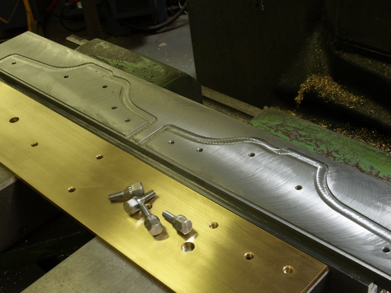
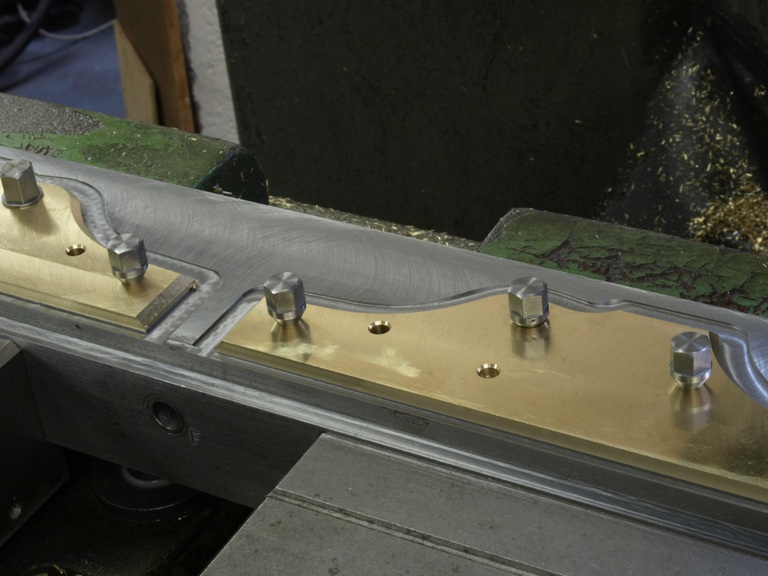
A13 set up and ready for side profiling
As you can see the rivet holes have a slight 60 deg chamfer the same as my jig screws. This assists the positioning on the milling jig and then again providing the retention for the riveting.
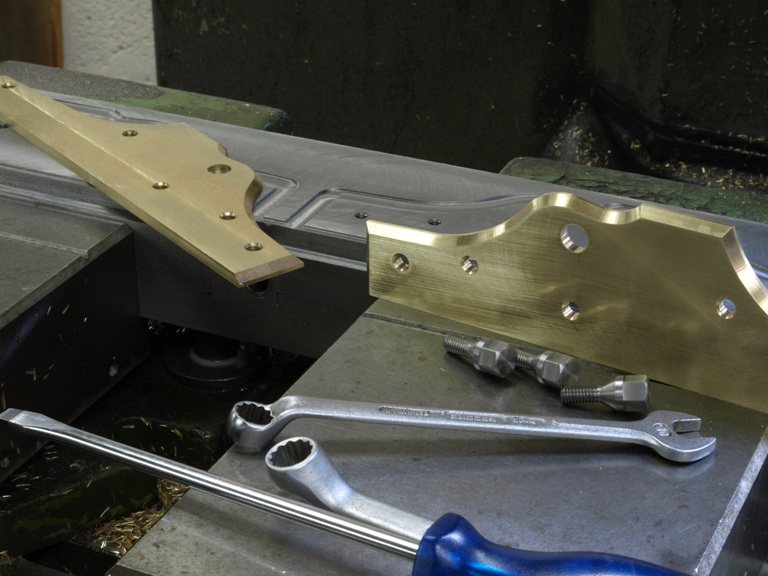
A13 sides removed after profiling and chamfering is complete. (There is no point in photographing this stage as it is the same as the A1 pictures shown previously in Window to my workshop 2)
Time to go home
Look out tomorrow!
