Karl Holtey – Blog Archive

February 20, 2012

Window to my Workshop 25

Spiers Style Shoulder plane – 1

It seems appropriate to start this blog whilst I have a picture of these planes on my website home page here.

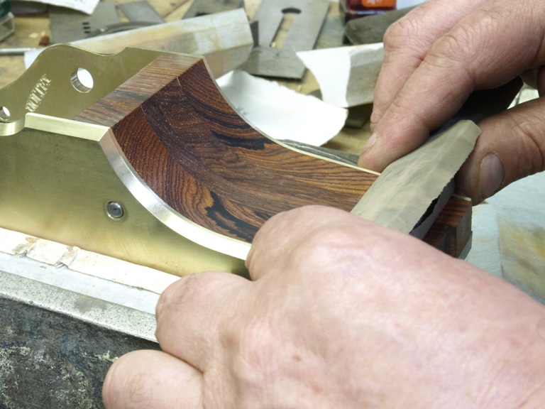
I don’t see myself making any more shoulder planes for some time. This style of plane is the only Spiers plane that appeals to me; in fact it is probably my favourite shoulder plane. The construction with its components is very much like the Norris A7 but has the shape I prefer. In the making of the Spiers I have had to make a lot of new tooling – for just six planes. As you follow this blog you will see some of my hidden work.

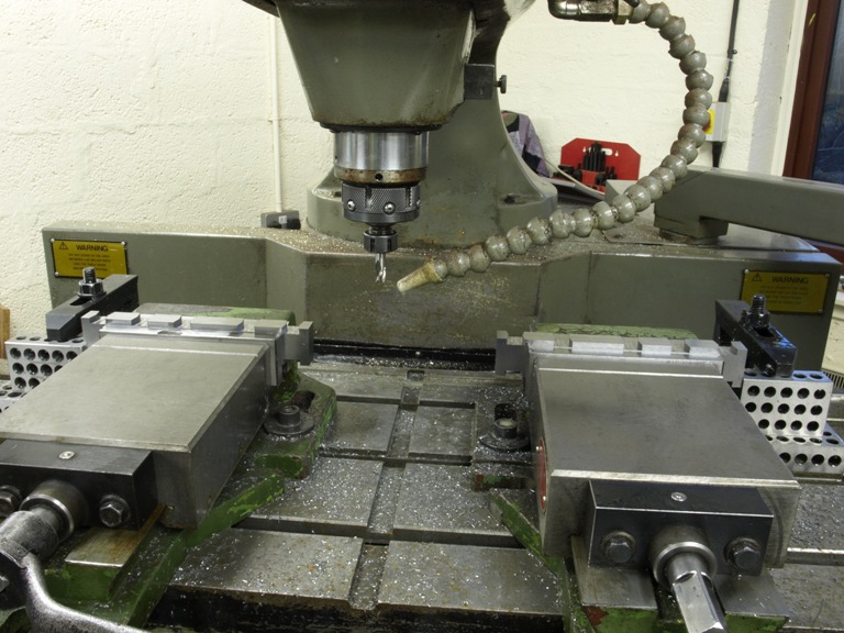
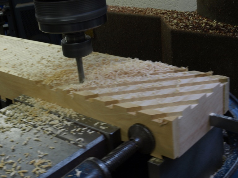
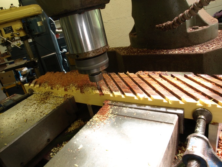
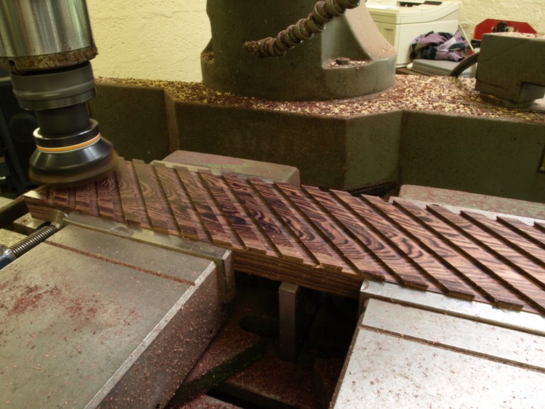
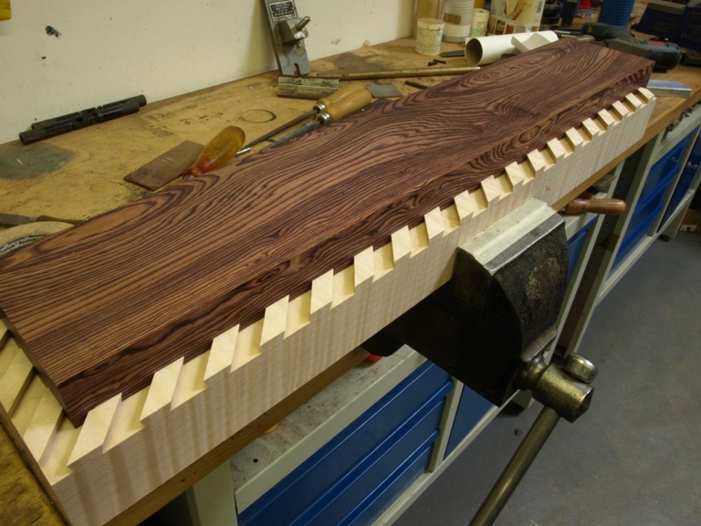
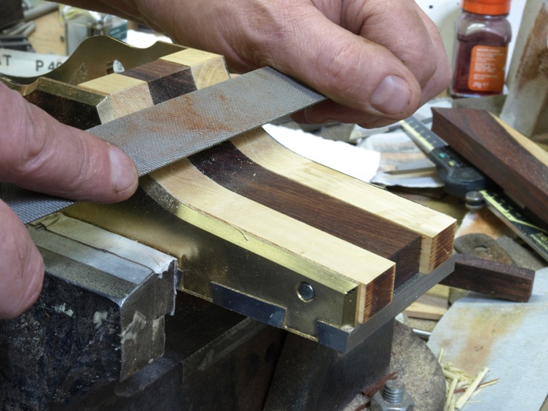
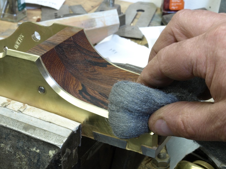
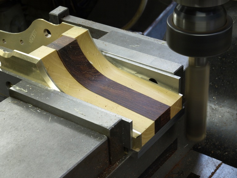
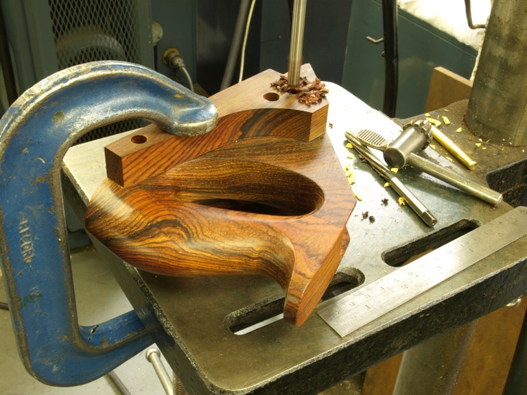
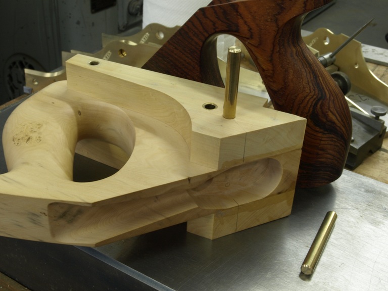
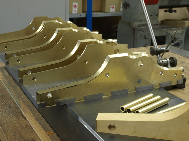
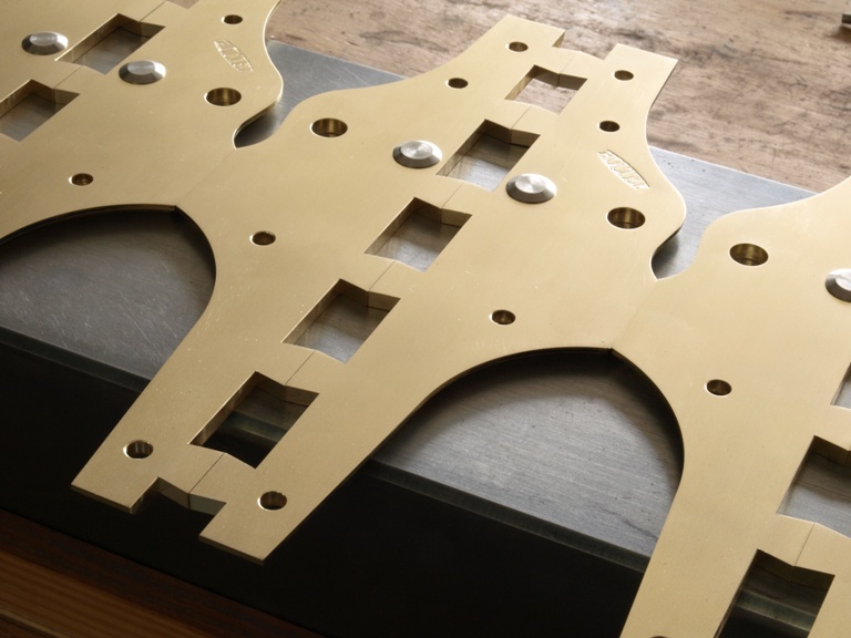
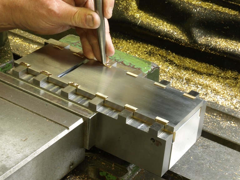
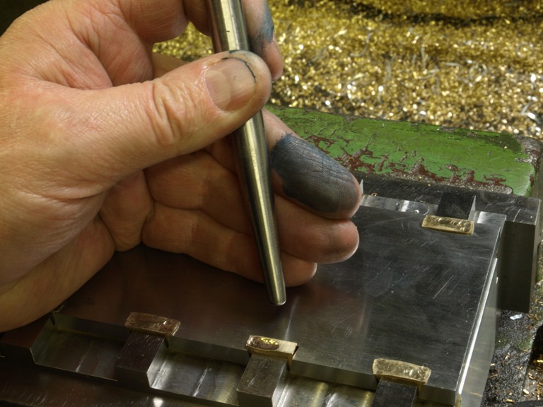
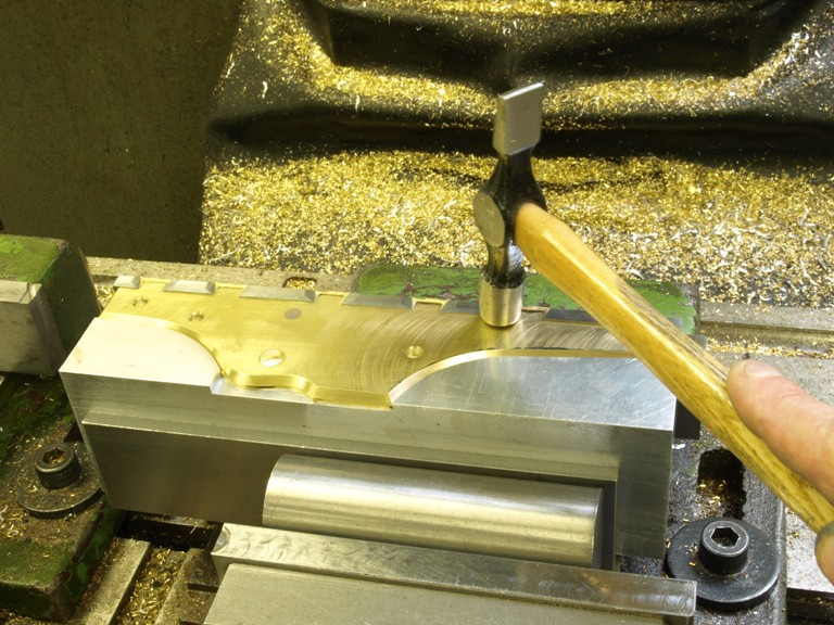
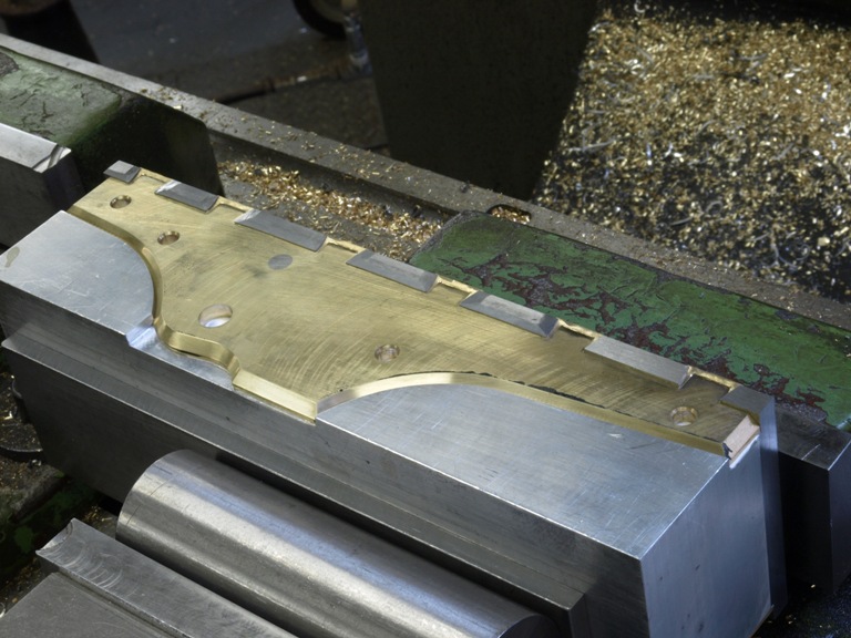
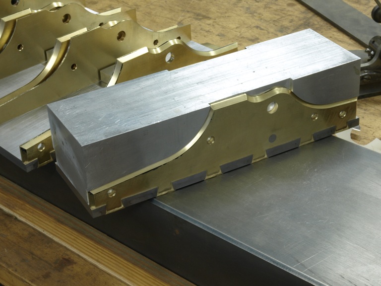
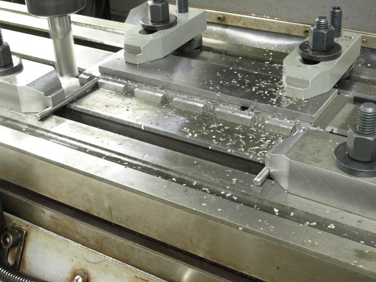
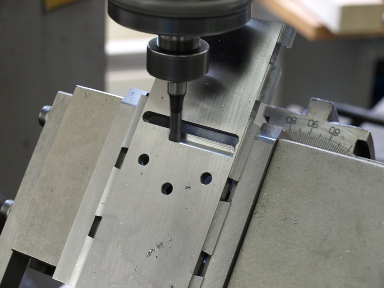
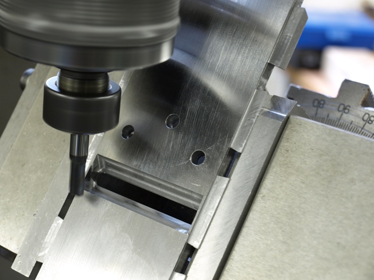
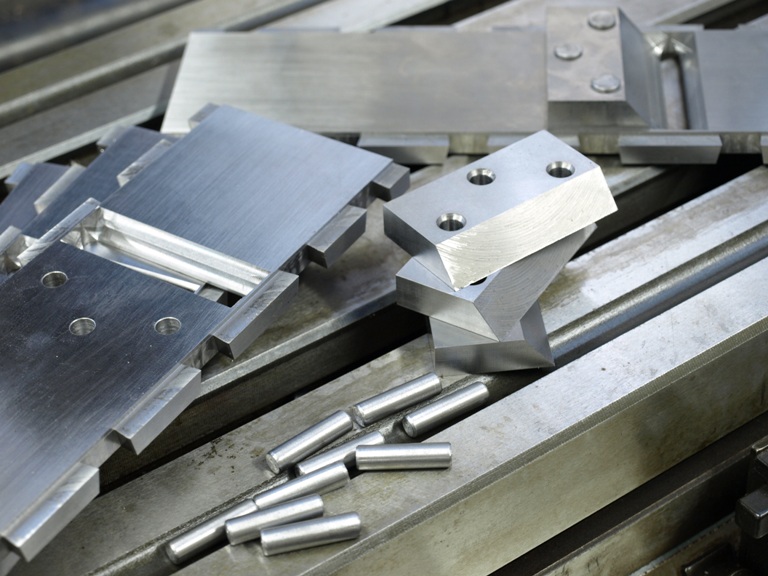
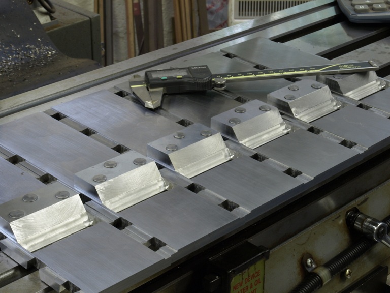
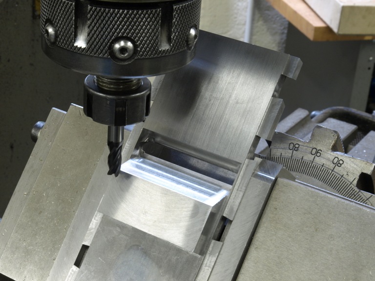
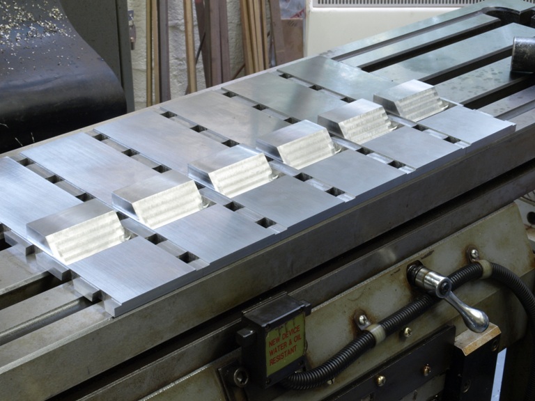
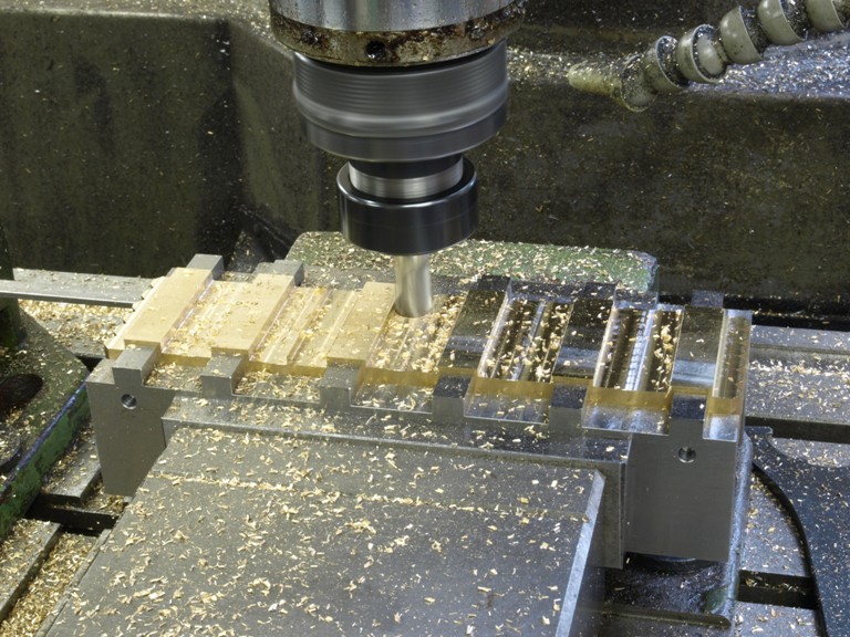
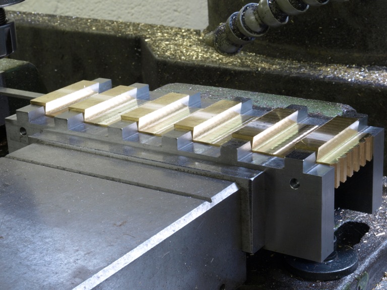
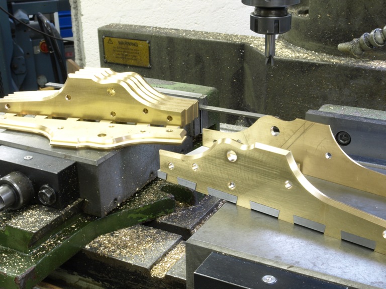
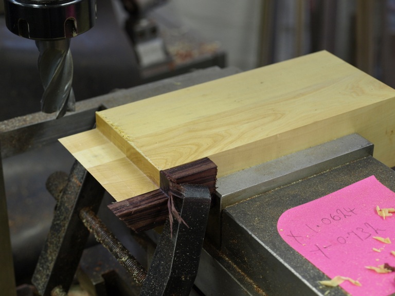
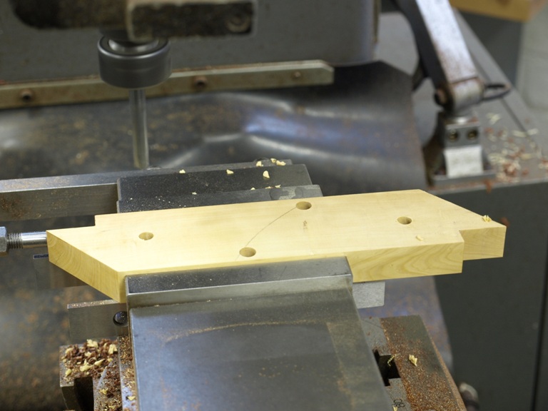
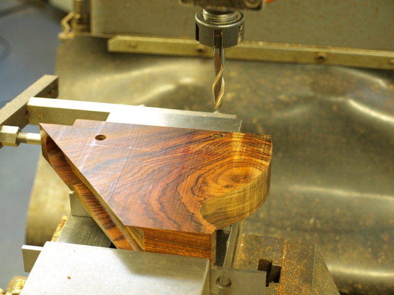
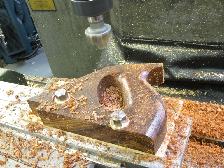
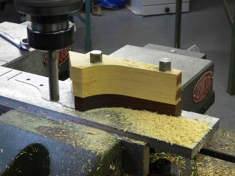
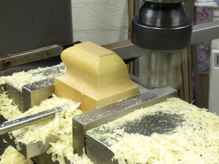
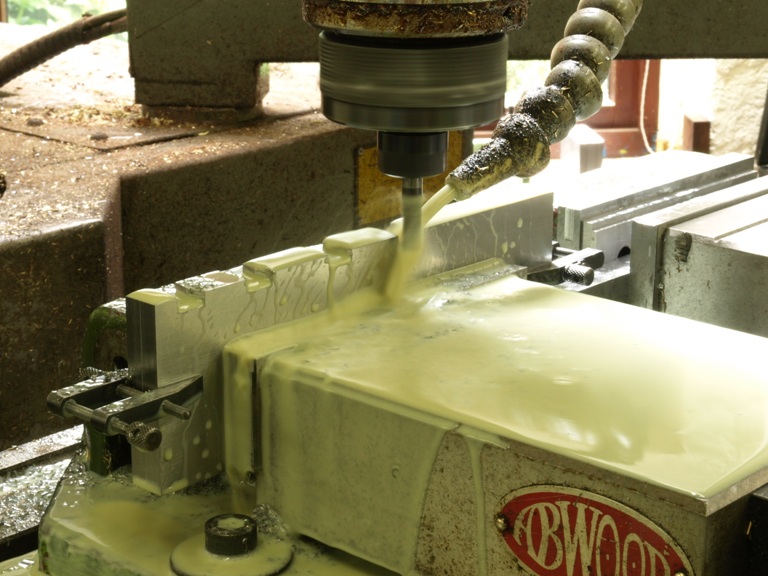
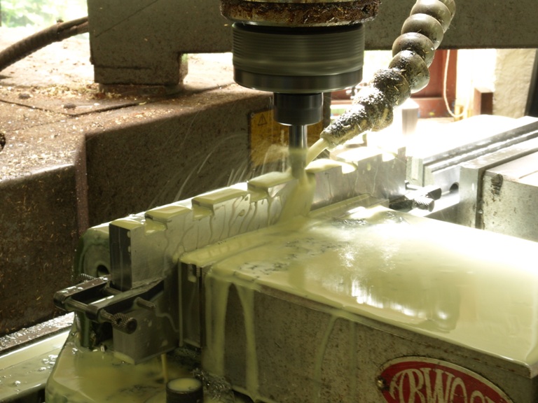
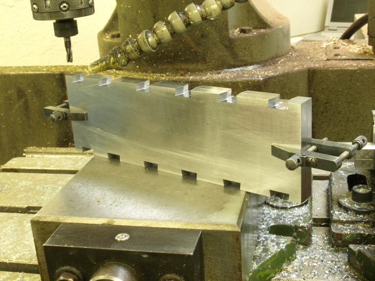
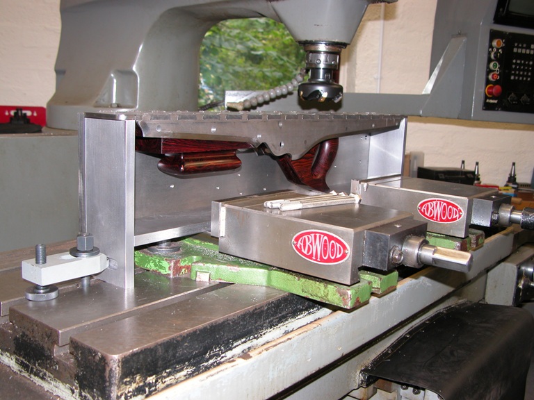
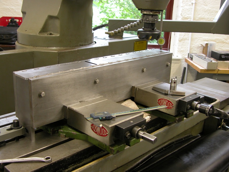
The following pictures show my familiar dovetailing of the bottoms being milled in pairs back to back so that I can form a compound dovetail. Please note that all the bottom blanks have been cut and precisionally ground all round in one piece (not separated at the mouth) at this stage.

(more…)

Window to my Workshop 19

Filed under: Transitional T21,Window to my Workshop — Tags: , , , — admin @ 4:44 pm

Holtey Transitional Jointer Plane – 2

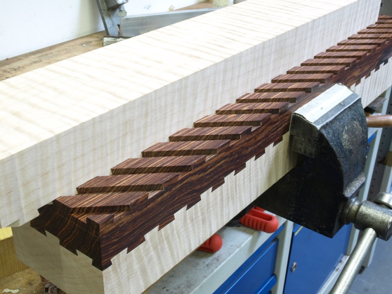
As there have been comments about this dovetailed jointing system I realised that I should show the pictures of the dovetailing in progress.

There are a few who know the dovetail puzzle of using a cube made up of two contrasting woods showing one dovetail on each side. In the case of a square object you cut the angle of 45 deg for the path of the dovetails (two) so that the joint slides into position with this angle, which gives an even sized dovetail on all four sides.

Once you start altering the dimensions and the number of dovetails then it becomes complicated. If it was not for my CNC it would be a nightmare.

The first cut for the dovetailing is done with a plain cutter so that I can reduce the mileage on the dovetail cutter.

With the grooving complete I can then follow through with the dovetail form cutter (tungsten carbide as on all my tools).

The depth of the dovetails has allowed for a final skim over the top to guarantee a uniform depth and also gives a neater finish.

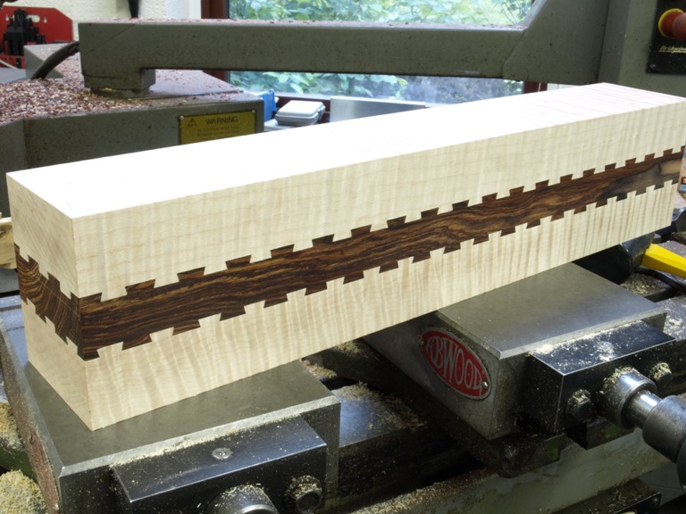
The exciting stage – sliding the dovetails together.

You will notice that some of the bottoms are to be cut to make two bottoms after they have been jointed and glued on both sides.

This is two bottoms waiting to be glued. The gluing is not so much for adhesion but in this application it is mechanical. The only way to undo this joint is by sliding so once the glue has hardened it becomes keyed to the texture of the wood. The dovetailing is a quantum leap from tongue and grooving used by other manufacturers.

For the gluing I have used polyurethane with an open time of at least half an hour – well that is what they say on the tin. In real life the comfort time is less than 5 mins. So preparation and rehearsal is necessary. I use the polyurethane so that I don’t introduce any more moisture into the wood. Also it expands so taking up any voids. I have a loose fit of 8 thou so that the joints are reasonably easy to slide together and still have a small glue line.

It is extremely important that the gluing should be done soon after the dovetailing because wood is unstable and it can fit today and not tomorrow.

Window to my Workshop 16

Filed under: A13,Conclusion,Window to my Workshop — Tags: , , , — admin @ 3:45 pm

Conclusion of making the A13 dovetailed infill planes

For a long time I have procrastinated in writing a blog, and in that time I have kept a library of pictures of plane making throughout my range hoping to document it over time.

With the A13 I have tried to give some idea of the sheer effort that goes into the making. Although I have missed out much of the story, I hope it is enough to provide an overall picture. I have shown the mixture of hand and machine work that is necessary to achieve something of this quality. Also, I hope that I have shown that the machine work is not an economy but a necessity.

I decided to make the A13 because I could see potential in this design and its very appealing aesthetics, and it has turned out to be my best seller. From the blog you will see that a lot of detail has been upgraded. Some of the enhanced contours have been copied by others and referred to as an A13 when in actual fact it is a Holtey designed A13 and not a Norris. The original Norris A13 was cast iron which supported a square bun. However the introduction of dovetailing (mainly brass on steel) and riveting through metal spacers are all my ideas.

With the completion of these few planes, I feel that I want to move on and look for a replacement for this infill design.

Window to my Workshop 13

Filed under: A13,Window to my Workshop — Tags: , , , , , — admin @ 3:01 pm

A13 dovetailed infill plane continued (6)

Parting off and trimming spacers which I use on all my infill planes for better dimensional stability.


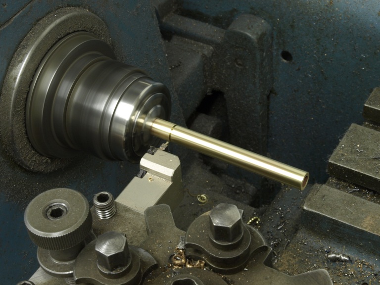
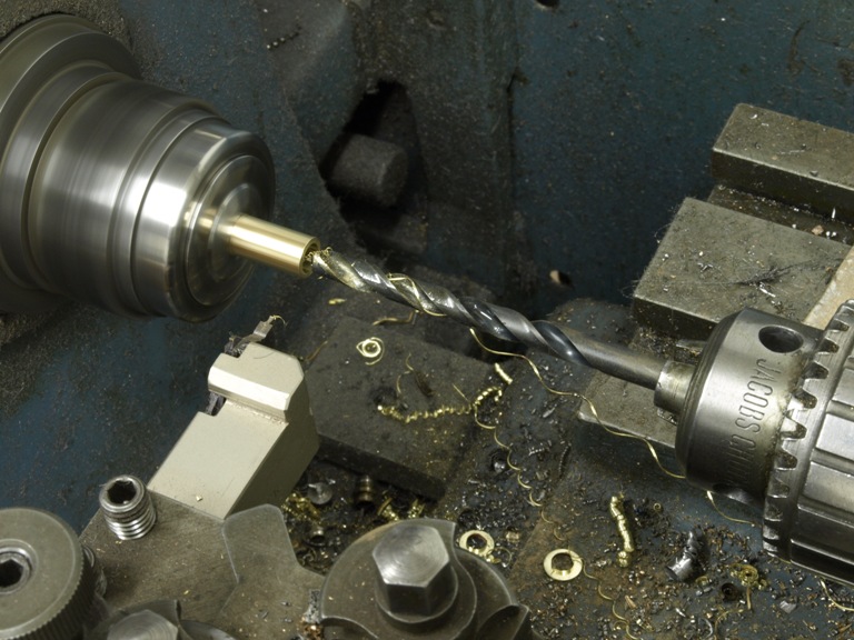
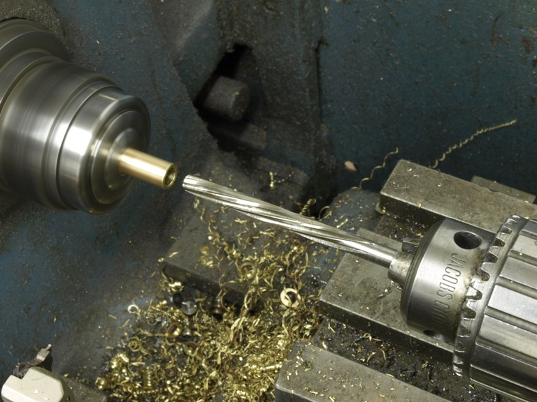
The spacers are drilled and reamed for the 7/32” rivet, from both ends for better concentricity.


Flushing off rear infill.

This is done with a temporary spacer to represent the handle as it is too difficult to do this with the handle in position. I also use sleeper rivets and spacers for location


The polishing is done after excess materials have been removed.


At this stage the plane with its infill can be put into the milling vice to flush the end. After further polishing the infills are ready to accept the handle.


Even without any machines this is one piece of equipment that everyone should have – just an ordinary drill press. This picture shows the drill press being used to drill the hole for the brass bar which is then drilled and tapped later on in situ for the adjuster fixing.


Inserting the brass bar for the adjuster fixing.

Window to my Workshop 12

Filed under: A13,Window to my Workshop — Tags: , , , , — admin @ 1:22 pm

A13 dovetailed infill plane continued (5)

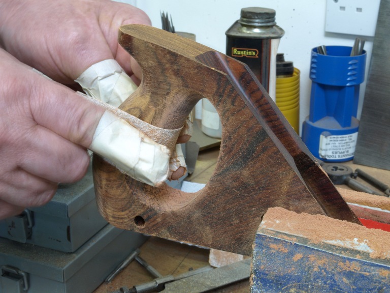
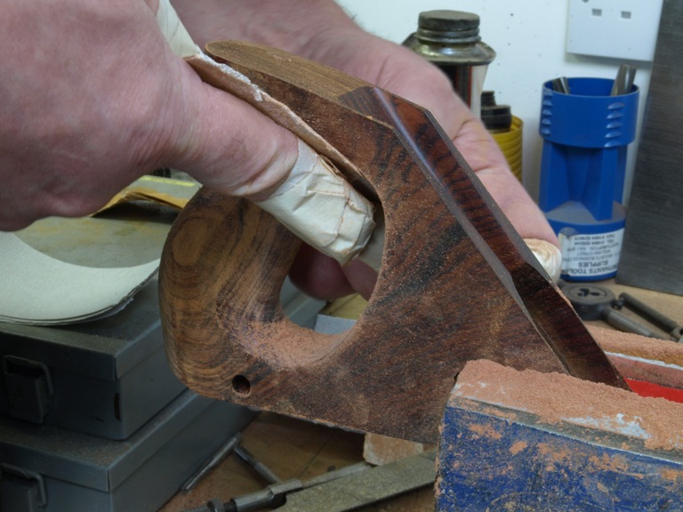
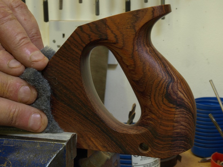
It is difficult to believe that these two pictures of the boxwood are the same handle. It is amazing what you can do with light.

This work is nice and easy but I find it a little tedious and boring. The start to finish on one handle is at least 2 days.

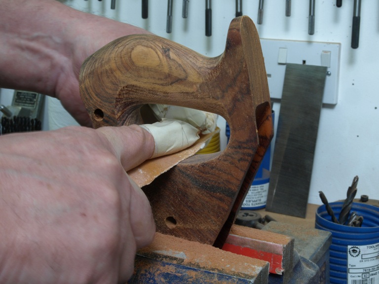
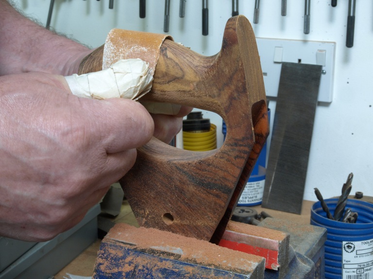
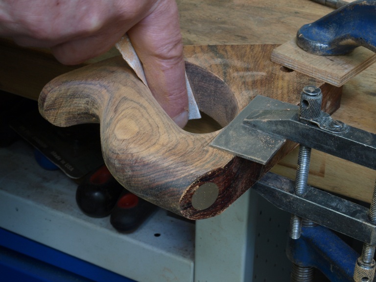
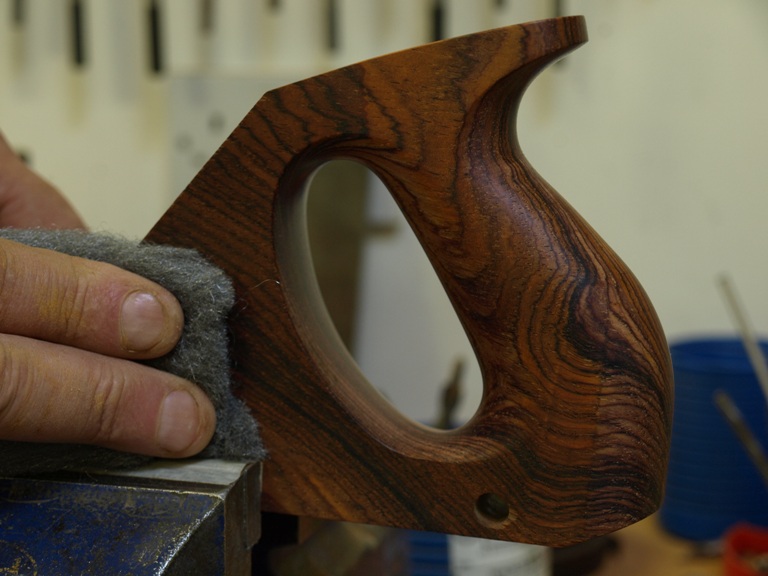
The abrading that you can see is particulary extensive as I have to remove every bruise or tear to the fibres which are left behind after the shaping. I start at 80 and work down to 400 grits. After using 600 grits then final finish is with 0000 steel wool.

Normally these marks are not seen when using polish but my chosen finish for wood infills is always oil. This is very clean, business like, mellows the wood nicely and is easy to maintain. The only downside is that the preparation work for oiling is considerably greater than for French polishing; this is because the finish has to be absolutely perfect as the oil will show up every scratch and blemish.

Four dovetailed bodies waiting for their infills.

Window to my Workshop 11

A13 dovetailed infill plane continued (4)

Some of the preparation work and then putting the metal parts together.

One of those tedious jobs – polishing the chamfers. As you can see these need constant blueing to maintain the true flat angle all the way round.

No, not a piece of origami!

The sides after chamfer polishing and blade kickers which seem to have appeared already riveted by the workshop fairies.

Peining the underside

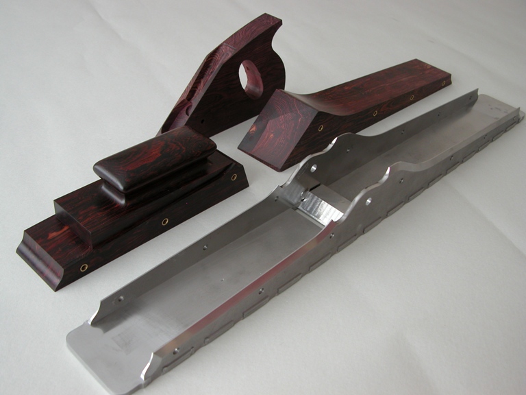
This is the first stage of peining. As you will notice the body is clamped onto an aluminium former by two surface ground steel plates. These are castellated to match the dovetails so that there is continuous pressure over the whole of both sides including the dovetails and prevents the space between the sides getting larger.

Peining the underside

With the sides and their dovetails firmly supported, I can then pein the tails by starting in the centre and working to the outside. Without this kind of support the sides would blow apart. The object is to expand the dovetails inside which normally cannot be reached as these dovetails are true compounds and not the illusions that are normally practised.

In short this clamping arrangement behaves like a die.

Side peining of plane

As you can see this is peined straight off the flat of the hammer. All the joints here are already tight and have not moved or wandered due to the clamping arrangement as described above. By peinning with the flat of the hammer it makes the metal expand and flow keeping all edges straight and maintaining the true dovetail form. Everything is sharp and crisp when flushed off.

The reason I do not use the punch here is because I am making the harder steel flow into the brass. The brass being softer would lose its form. Care is needed as a missed hit could leave an unwanted ‘dink’ in the side of the plane.

This is after the peining, but showing one dovetail left undone for comparison.

The plane body after dovetailing showing the precision aluminium former.

Window to my Workshop 10

Filed under: A13,Window to my Workshop — Tags: , , , , — admin @ 12:51 pm

A13 dovetailed infill plane continued (3)

Here I describe some of the work to the bottoms of the planes. This is an area where most of the work of the plane is. It is probably light years ahead of any other infill plane.

Rebate to dovetail

Machining stops to the dovetailing, this adds extra support to the plane sides and also provides a light stop. This is something I currently do to the shoulder planes and it will be a new feature to all my dovetail planes.

Roughing out bed area to mouth.

This area is rough machined prior to the frog fitting to facilitate better access around the mouth.

Milling to the front side of the mouth

This is one of the main reasons for leaving the finishing of the bed until last so that I can access an end mill to the front side of the mouth.

Frogs waiting for riveting

Now that 80% of the work to the mouth area is complete the frogs can now be riveted.

As you can see that most of the surfaces are surface ground and especially the contacting surfaces which will be air tight once the frogs are riveted. This is not achievable with filing.

Frogs after riveting.

All that remains now is for the flushing of rivet heads and the bed machining.

Finishing cut to blade bed

Work holding for bed working

The highest standard of bed working on a true plane with no azimuth error and the bed pitch is exact to 51 degrees to within 1 minute. This might not seem that important but it is to me because I know where everything else goes then. I want to know exactly where the pressure points are when the blade is clamped.

Plane bottoms complete

This is a nice sight for me as it is a milestone in the project. Once this is achieved I am a happy bunny.

Roughing out the dovetails

I usually do these 6 pairs at a time and it takes several pecks especially with brass as it tends to chatter more than steel.

At last the final dovetail cut

Checking for fit.

Now we are starting to look like planes.

Window to my Workshop 9

Making of A13 part two

Much of the infill work is always trued up flat and square before any of the work commences, as in most woodworking projects.

In this picture are the rear infill sides showing the frog area routered away and this gives me a datum stop which helps me work out the drilling positions and its position in the plane. This will also be the same with the handle.

This is one pair of A13 rear infills being drilled for rivet spacers. Note the frog cut out being used as a stop. After this is done then I can drop a template over the holes to mark out the cutting line for band sawing.

This is the handle being drilled for rivet spacers using the same stops. As you can see I am making planes with rosewood and boxwood at the same time.

Whilst the holding fixture is still in position on the CNC milling machine it is prudent to use this for other work as all the datum positions are set up. Breaking down and setting up can be very time consuming and a little tiring on the grey cells.

This picture shows the finger hole and handle being roughed out.

As I have said; taking advantage of the holding fixtures before they are taken down.

This is the final cut after using the band saw to cut the infills out. I use the CNC mill to cut the true form of the sides. I add on a few thou all round for better finishing.

Using a manual milling machine with a purpose made cutter to produce a moulded form on the front bun. This is very accurate on a milling machine especially equipped with a DRO.

Milling the dovetail pins on the A13 plane bottoms.

Milling these is very advantageous on a CNC milling machine as I can work two bottoms together face to face in mirror form. I have a left and a right side of the bottom being worked together. With a dovetail form cutter and tracking in a butterfly pattern this allows me a left and right cut. I use three different cutters for this process – roughing, finishing and form cutters.

After cutting the compound dovetails in the plane bottoms.

At the risk of criticism from the purists I will say that with some very careful setting up I can produce a near perfect fit between the sides and the bottom without filing.

Special

Filed under: Specials — Tags: , — admin @ 12:14 pm

A photograph following the comment from Dave:
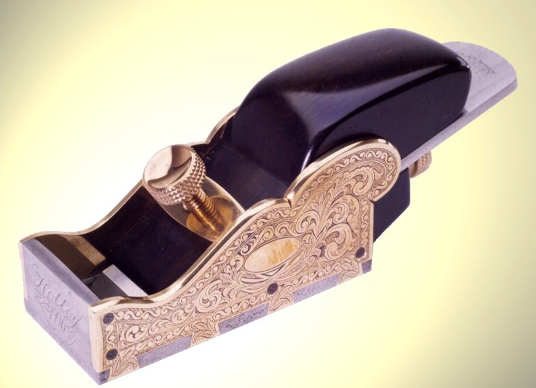
A project like this is priceless.

Comments »
1.
Thanks for this blog. I guess things i didn’t understand i now understand. Just the thought that goes into saying that abrasion whilst pushing the plane down will flex the plane making it not flat staggers me in it’s depth, or perhaps my own shallowness of thought.

There are few real toolmakers left that don’t have hydraulic arms and computer memories, and i think i understand why you are teaching us all what you do.

That you haven’t made your “fortune” doing this only further convinces me that a true artisan, someone who can make something beautiful of practical use, is the pinnacle of our society.

thanks

nik

Comment by nikpalmer — July 16, 2009 @ 7:21 am |Edit This

2.
Hi Nik

Thank you for your observations and nice comments.

k

Comment by admin — July 17, 2009 @ 1:45 pm |Edit This

3.
REAL VALUE ?

The lady on reception told me to take a seat and help myself to coffee; my relationship manager would be with me shortly. As i waited, I peered at the cars raised above the surgically clean workshop floor, as men in overalls and latex gloves busied feverishly below them. You have to hand it to certain car companies, at least they hold your hand while they kick you in the nuts !!!
So, how would you feel about a handplane that halves in value every year, until you have to pay somebody to take it away ? And what about getting charged huge annual sums to keep it maintained ?
It’s not a new argument but it is one we will revisit in reference to a Holtey handplane.
Brand wise Holtey is the equivalent of my motoring marque. Both companies have a long, distinguished history, they treat their customers well , they’re making greater efforts to source certified materials and use them responsibly, and they deal fairly with there suppliers and dealers to ensure a profitable and sustainable business.
The crucial differences, however, are that Karl Holtey handplanes hardly devalue at all, (in fact in the long term they will probably pay you)and cost absolutely nothing to maintain. Still many uneducated tool lovers see them as overpriced, Obsessed with finding the ’same’ thing for a lower price.
The uncomfortable fact might just be that there is no such thing as a free lunch !
In short: can I afford a 982 ? Nope, but does that mean its too expensive ? Now that is a completely different question.
Food for thought, perhaps.

Comment by Archie. — July 17, 2009 @ 8:21 pm |Edit This

4.
Hi Archie

Thank you, your thoughts are very much appreciated.

k

Comment by admin — July 17, 2009 @ 10:58 pm |Edit This

5.
I went solo on Roiters miller, Ive got my solo pictures to prove it, so how many people can say that, I even entered it in my flying log book, so now Ive dined at the kings table what else is there? jog on
regards Gary and Jes

Comment by Gary Bennett — August 22, 2009 @ 11:22 pm |Edit This

6.
Hi Gary

At least you got the pictures – I didn’t get one when I went solo

k

please see comment under workshop 10 for explanation!
June 29, 2009

Window to my workshop 5

Filed under: Window to my Workshop — Tags: , , , — admin @ 1:32 am

Flattening an infill plane

This is probably about one of the most difficult areas in the making of a dovetailed infill plane.

The amount of forces and stresses generated from the peining usually causes the whole structure to convex depending on the force of the peining.  The longer the plane body the greater the amount of movement at the centre of the plane.  Flushing the dovetails off after the peining will not straighten the plane out.  The only way to flatten the sole is with a milling machine, rubbing the sole of a plane on an abrasive surface is not going to work.  However most planes will still work if they are not entirely flat, but this isn’t that kind of tool.

After peining, the amount of removal necessary to bring about a flat surface would be far too much for filing or abrading.  The abrading system practised by quite a lot of people would only level off the high spots.   The pressure applied to the plane to do this will flex the body of the plane to try and match the surface you are pushing against only to spring back once you release it.  This usually means that you will still have a plane with a camber or a twist.

A1-28.5-work-holding

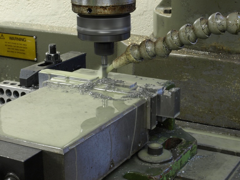
The body of a plane can be very difficult for work holding.  It would be very expensive to make a jig for this purpose, so for the small number of planes that I make I have chosen to improvise as shown on the above picture.  This shows one side open so that the plane can be seen. 

 At this stage the dovetailing on the sides will only have been partly flushed so that they will stand a little bit proud and I only clamp along this narrow line.  There is no contact on the sides but just along the bottom line i.e. dovetail line. The reason for clamping along this narrow line, assuming that there is the usual slight twist,  is it will clamp the plane body without changing its shape within reason and this will then allow any twist or deformations to be removed.  If I was to clamp directly on to the sides of the plane then I would only change the shape of the plane which would spring back the moment it was released from its work holding jig.  Of course the removal of this excess material  is done with a very fine cut and the correct tool, no heat must be generated whatsoever.

Although time consuming this system does work and I can achieve some tight tolerances of +/- .0015.  This is only a way of removing the excessive material. The rest of the flattening process is another story.

There is no way at any stage I could use a surface grinder on an infill plane as this type of plane is a  thin walled box section and as grinding generates heat the structure would be compromised.  This would make the whole process impossible.

This is my holding jig shown with the last clamping plate in position.

A1-28.5-parts

A picture showing the main parts of an A1 28 ½” jointer but with a long way to go.

Older Posts »

Powered by WordPress